


Introduction
The VPFlowScope® compressed air flow meter is designed around a unique measurement principle. This enables you to measure not only the magnitude of the flow but also the direction. Why is this important? In this article, we will show two examples where bi-directional flow measurement plays a key role to come to the right conclusions. In the first example, we will describe the case of an electronics manufacturing plant, which has a large interconnected ring network with two compressor rooms, located in different buildings. The two compressor rooms are about 500 feet apart. In the second example, the effect of flow measurement upstream of a local receiver tank is described.
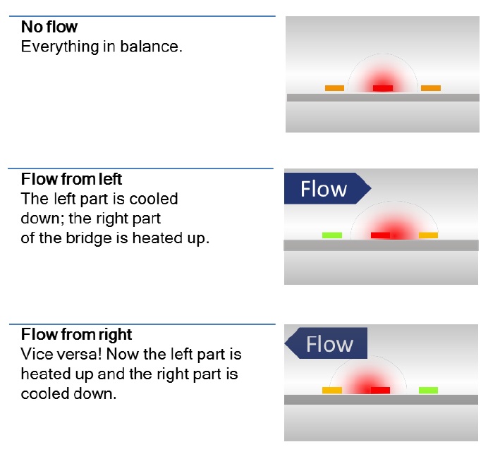
Thermabridge™ technology
World’s first thermal flow sensor made in a silicon (not silicone!) chip was invented 40 years ago by one VPInstruments’ founders, Anton van Putten, back in 1974. His unique design can be seen as the blueprint of many thermal mass flow sensors, found in automotive, HVAC and industrial applications. The original Thermabridge™ sensor combines flow direction measurement with thermal mass flow sensing over a full 0…150 mn/sec range. This enables you to measure flow in complex ring networks, where any other flow meters would deliver very unreliable measurement results. Who would have thought that his invention would become so important for accurate compressed air measurement?
Case 1. Two compressor rooms
At a large electronic component manufacturer, compressed air is used for the entire production process: injection molding machines (handling and packaging of products), picking and placing of components, plating and galvanizing metal parts. An energy management program has been initiated to reduce the overall energy consumption of the plant. Compressed air was one of the utilities that needed attention. The compressors in the factory were quire old (> 10 years) and there was room for improvement, from an efficiency point of view. To select the right compressor, the demand profile of the factory needed to be measured. But the company realized that permanent monitoring is key to long term savings. So instead of hiring an audit firm to perform a temporarily audit, they selected VPInstruments to implement a permanent monitoring solution. Which could eventually be expanded towards other utilities.
Initial goals for phase 1 of the project were:
• Establish a base line profile
• Select a replacement compressor (combination) based on this profile
• Identify waste, and reduce air demand of production areas
During phase 1 of the project, we installed four flow meters, to get a clear picture of the average demand. But after a couple of months, we encountered an interesting situation where standard uni-directional air flow meters would provide useless results. In this particular situation, back-flow towards the receiver tanks caused wrong readings, resulting in severe measurement errors.
System description:
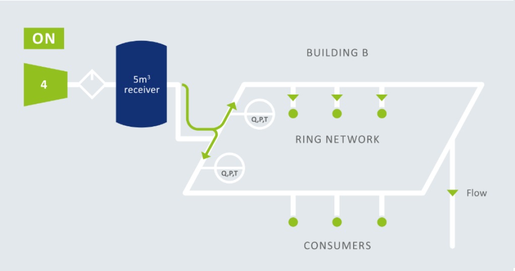
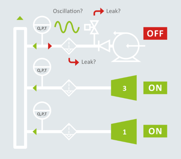
The cartoon below shows a simplified layout of the compressed air system. The compressed air system consisted of two compressor rooms (A and B). A compressed air ring network is supplied from these two separate compressor rooms. The compressor rooms are controlled with a pressure-based control system.
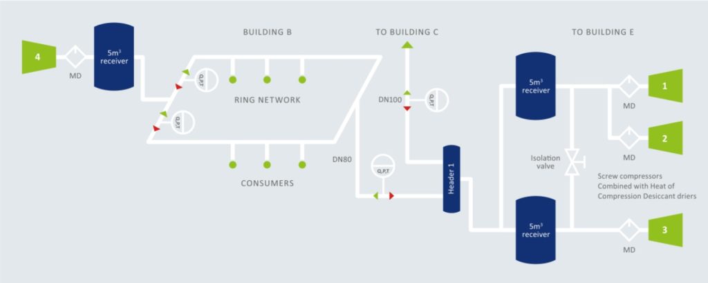
At compressor room B, two flow meters are installed in a ring network to measure the air delivered to the network by a compressor. Between this compressor and the network, a large receiver tank (5 m3) is installed.
In room A, three Atlas Copco screw compressors were located (ZR3A, ZR3A, ZR145). The machines were used for the daily baseload. Each compressor is fitted with a heat of compression drum drier. Between the pipes and the compressors, two large receivers are installed, 5 m3 each. From the receivers, two separate pipes supply air to the production processes.
One pipe is connected to another building where compressor room B is located. The distance between the two compressor rooms is approximately 500 feet.
Reverse flow or not?
After taking a closer look into compressor room B’s configuration, we came to the conclusion that there has to be reverse flow when the compressor is turned off. The following pictures explain this effect in detail.
Compressor in room B off: receiver tank behavior
During unload and off hours, the two uni-directional flow meters showed consumption, while one would expect zero flow. The large receiver tank is filled by the other compressors (from room A) when the local air demand in the ring network is low, and it delivers air to the network when the local demand is high. You can see the receiver tank as a big balloon interacting with the network.

Compressor in room B on- “ merging traffic” situation
When the compressor is running loaded, compressed air is fed into the ring network. In the T-junction, the flow merges with existing “traffic” based on how the consumption in the ring mains is balanced. If the consumption is well balanced, it might be perfectly symmetric (50% left, 50% right), but when the consumption on one side is much higher, the airflow will distribute differently. Pulsating demand can also change the flow distribution for a short period of time.
The air coming from the compressor merges with the air which was already flowing through the ring network. This can result in a high or low reading, depending on the actual demand and the resulting flow direction.
Uni-directional versus bi-directional
A uni-directional flow meter does not have a clue where the air is coming from. This results in large errors. This applies to most thermal mass flow meters based on thermal dispersion, constant temperature anemometry and so on. Other examples of uni-directional flow metes are vortex meters and turbine meters, when read out via a standard pulse transmitter (the actual counter on the turbine meter will turn backwards). Venturi’s are also uni-directional. The differential pressure signal will not change to negative when flow is reversed. Orifice meters can also measure reverse flow, but they are not so suitable for compressed air due to their permanent pressure loss.
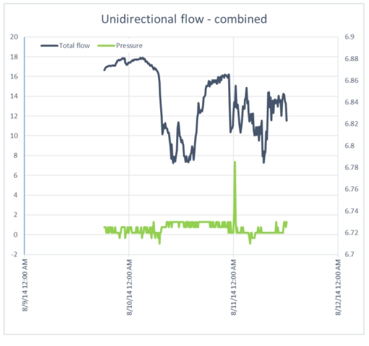
By turning on the bi-directional sensing feature of the VPFlowScope, the changing of flow direction is instantaneously revealed. Now the reverse flow shows up in the graphs as negative values. Lets take a look at some real data: In the graphs below, we zoom into a specific period of the measurements in compressor room B. The original data, from the bi-directional flow meters, has been processed to show the difference between bi-directional and uni-directional flow.
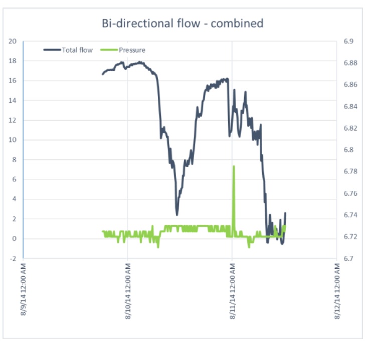
At the end of this period, the effect can be seen very clearly: The compressor turns off In the left graph where the two bi-directional flow meters cancel out each other, the resulting flow is nearly zero. In the right graph the flow is not cancelled out, resulting in an artefact signal of nearly 13 m3/minute.
Uni-directional is good enough?
One could say: why not correlate this with load/unload data from the compressor? When the compressor is in unload or off state, you know that the flow is zero, so you can compensate for it. We think this is not the best way to solve the reverse flow problem, as there might be other (real) reasons for reverse flow, which would remain unnoticed. For example, a leaking non-return valve, a leaking seal or a blow-off valve. In this particular case, we found a leaking compressor seal. This leak could have costed 1,314 Euro per year and it took only 500 Euro to fix it. Another leak was found in a dryer. Again, this leak is upstream of the flow meter, so it would remain unnoticed when the flow meter is unidirectional. Savings: 2,102 Euro per year. Fixed for 100 Euro by replacing a hose.
Case 2. Decentralized receivers
In some cases, a decentralized receiver tank is used to “shave off” the peak load on the network. For example, when a machine has a large intermittent consumption profile. A question often asked: where to place the flow meter, and what will the flow meter show us when the machine has been turned off. This part of the article is based on an older audit at a potato food processing plant, where we used a standard thermal mass flow meter without bi-directional sensitivity. The picture below shows the setup.
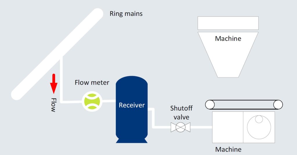
Test setup: The point of use flow meter was installed in between the receiver tank and the ring mains. Why? Because there was not enough straight length downstream of the shutoff valve.
The auditor called us after a couple of days, to discuss the results. The flow meter showed significant consumption while the machine was isolated from the network. The receiver tank was simply acting as a local buffer for machines further downstream the line. It was filled, and emptied at the pace of their consumption, causing significant readings on the thermal mass flow meter. In this case, the issue was finally resolved by ignoring the data during the period when the machine was shut off. But in other cases, there might not be a way to correlate local actions or events with data. In those cases, when looking at data from a unidirectional flow measurement device can lead to wrong conclusions.
Other issues you can discover with bi-directional sensors:
Bi directional flow meters can reveal important issues in many compressed air systems. In this article we described two cases where bi-directional sensors are crucial to draw the right conclusions.
Other examples where you can reveal issues:
Leaking non-return valves just after the compressor, or leaking condensate drains. The bi-directional flow meter will tell you when it happens.
- Leaking drains in the oil-demister, or under the wet receiver tank
- The non-return valve does not shut off completely
- The blow-off valve does not close completely
- Oscillations in the pipe network are seen as consumption instead of near zero flow
Conclusions
• For flow measurement in ring networks, bi-directional flow meters are key to correct results.
• Only Bi-directional flow meters can provide correct data when installed between receiver tanks and the compressed air network.
• Uni-directional flow meters will show a positive flow when reverse flow occurs, which can lead to wrong conclusions about the system behavior.
• With modern energy monitoring software, bi-directional flow meters can be combined in a virtual channel.