

Introduction
In this article we look at measuring instruments for relatively low gas flows, from a few cc/min to 1400 ln/min and pressure up to 14 barg. In this application area the most frequent used meters are VA meters, Differential pressure and gas mass flow meters with the thermal bypass concept. Most units used are mass flow controllers (MFC) but you can also purchase gas mass flow meters (MFM). An MFC is a flow meter equipped with a control valve and integrated PID controller. The user can provide a setpoint to the MFC that generates and maintains a defined gas flow. You also have Mass flow meters with an integrated needle valve to manually adjust the flow.
Beside the ones mentioned above there are some less known special types of flow meter technologies that often offer solutions for special applications. In this article we focus on the bypass thermal flow meter principle.
There is not one “best flow meter”. Everything depends on the application and what the user expects from the unit.
Measurement concept
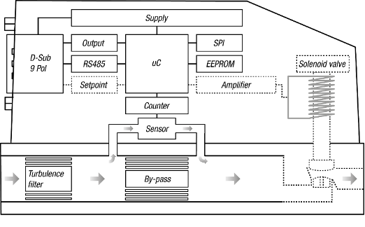
In the thermal bypass concept most of the measured gas flows through a bypass. In the bypass is an element that generates a very small pressure drop. As a result, a small percentage of the gas runs through the sensor, which runs parallel to the bypass. This sensor measures the gas flow, which is representative for the total amount of gas through the device. Each instrument is built for a specific gas and a defined measurement range.
Mass flow meters (MFM) and mass flow controllers (MFC), the names speak for themselves: these instruments measure and regulate the gas mass flow. For instance, in Kg/hr or ln/min.
There is a distinction between the MFCs based on a capillary sensor and instruments with a MEMS (Micro-Electro-Mechanical System) sensor. Both sensor techniques have advantages and limitations. The word “cons” is here deliberately avoided, because there are no bad measuring instruments. Preference should be driven by the application.
The capillary sensor consists of a thin steel tube (0.2 to 1 mm o.d.) around which 2 very thin platinum wires are wrapped. The platinum wires act as electrical resistance and are part of a Wheatstone bridge. The resistance value of the platinum wire depends on the temperature. There is a current going through these wires, which heats them up. At zero flow are the resistance is the same, but when a flow goes through the sensor there will be a difference in temperature that will be detected by the electronics.
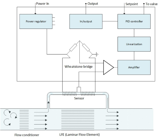
An MFC with a capillary sensor is equipped with a Laminar Flow Element (LFE) in the bypass. This LFE creates laminar flow behavior, just like inside the sensor. This means that the relationship between the flow through the sensor versus the flow through the bypass is almost linear over the measured range. Due to this linearity it is possible to calibrate these MFCs with a simple gas like air and use a known factor to make the meter suitable for other gases, including exotic, explosive, poisonous or inflammable gases.
The MEMS-based MFM/MFC has no LFE but a regular by-pass. The function is to insure a defined percentage of the total gas flows through the sensor. The bore of the sensor is much larger, so that for example the pressure drop is relatively low and the sensor less sensitive to pollution than a capillary. A MEMS sensor is also a lot more sensitive and due to that a turndown of 1000:1 is obtainable (versus 50:1 for capillary sensors).
This type of MFM/MFC must be calibrated with the gas as used in the application. The advantage is that the instrument thereby is more accurate. For some exotic gasses a correlation is possible, although the repeatability stays excellent, the accuracy will suffer.
The biggest advantage of the MEMS sensor is, however, that there is no (measurable) drift.
Drift is a slow shift of the zero and the measured value at a given flow. Drift affects the accuracy.
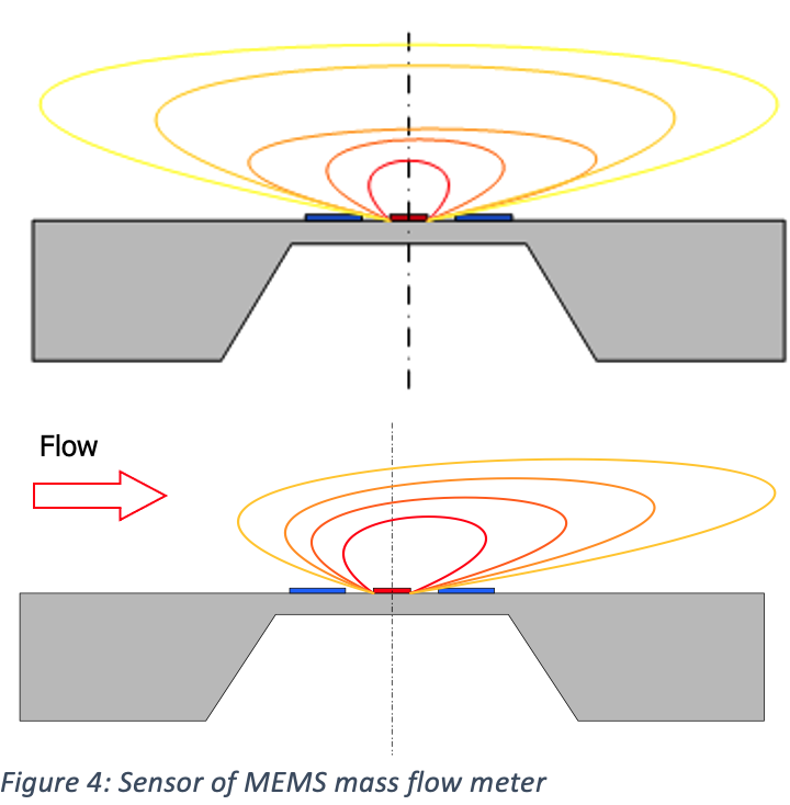
The MEMS sensors consist of two or three temperature sensors and a heater, vapor deposited as an extremely small molecular layer on a thin membrane. Conceptually the MEMS is sensor low-energetic and due to the membrane thermally and stress isolated. This insures that MEMS sensors are free of any mechanical and thermal stress. An additional plus point: the sensor is part of an electronic circuit all mounted on the MEMS. The measured signal is immediately digitized on the MEMS itself. No bad connections, no EMC distorting the signal,
These are the main reasons why MEMS sensors are without drift and maintain a long-term accuracy, reproducibility and reliability.
The instrument does not need the zero to be adjusted on regular basis. (for capillary MFC’s a standard routine). MEMS-based MFC’s offer significantly better reliability of the measured and/or regulated flow.
Summary:
Both concepts have their strong and weaker aspects. The capillary sensor in combination with the LFE leads to a reasonable linear relationship between the flow through the sensor and bypass. Due to this it is possible to use so-called K-factors, a multiplier factor between two gasses. This means that for applications with corrosive gases you can calibrate with a safe gas like air and apply this K-factor. On this way the units can measure reasonable correct with a corrosive gas.
For the MEMS-based MFC’s we have better specifications when it comes to accuracy, response time and turndown. Because the use of K-factors is not possible, any instrument with the gas of the application to be calibrated. The restriction is that these MFC’s not suitable for each gas.
Some MEMS manufacturers go a long way to temperature compensate their units, this results in a better accuracy over a wider temperature range.
A crucial advantage of the MEMS-based MFC’s is the zero drift in the sensor. That results in a better long-term accuracy, repeatability and reliability.
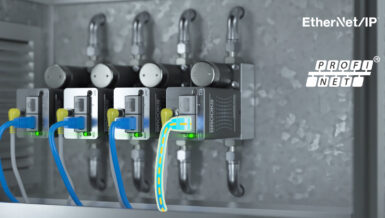
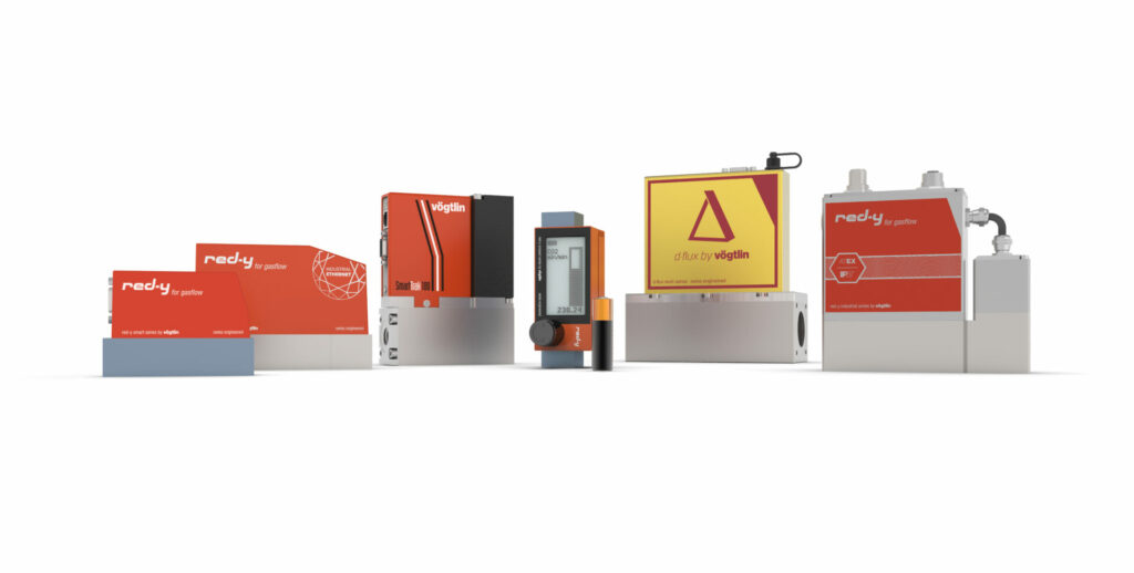
High-precision Thermal Mass Flow Meters & Mass Flow Controllers for Gases
Reliable technology and industry-standard interfaces make the red-y smart series thermal mass flow meters (MFM) and mass flow controllers (MFC) particularly suitable for measurement and control in gas delivery systems and plant engineering applications.