

This article outlines the importance of assessing process risks and designing effective pressure relief systems accordingly and provides guidance to ensure that your systems are up to the task.
Introduction
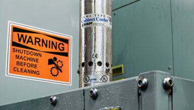
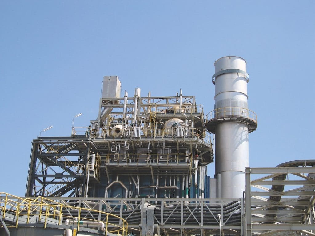
State-of-the-art design of industrial processing plants involves the extensive use of preventive measures to avoid hazardous situations. Specific measures must be taken to prevent the pressures inside of processing equipment from exceeding safe, acceptable levels. The use of instrumentation to intervene where pressures may exceed the acceptable threshold is a common approach.
The objective of plant operators is to achieve maximum operating time without unplanned interruptions due to excessive pressure incidents. Despite the use of highly sophisticated risk assessment modelling, the risk remains that critical safety instrumentation may not be functional when needed. Where hazards such as excessive overpressure or vacuum pressure cannot be avoided, pressure relief devices – mainly safety relief valves and/or rupture (bursting) disc devices – are commonly used to protect the pressurized systems from catastrophic failure.
Preference should always be given to inherently safe design solutions. The relevant design criteria should include an assessment of risks and special operating conditions that could strongly affect the operational characteristics and flow capacity of the safety relief system. To avoid impeding the anticipated safety level of the installation, extra attention may be required by the safety system designer.
This paper describes the role of pressure relief systems, recent changes to the pressure relief system standard, and how risk assessments and risk mitigation improve design decisions.
Managing the Perils of Excessive Pressure
Pressure relief systems act as the last line of defence against overpressure events in process plants. Aging and modified infrastructure, combined with a reduced level of on-site expertise, has left many plants and refineries with relief systems that may place people and assets at risk. With tightened budgets, lower resources and a growing list of “must do” issues in maintenance, relief systems are unfortunately often not given the required priority.
One of the most critical steps in establishing the appropriate configuration and settings of individual safety system components is assessing the risks in the process. The assigned engineers need to consider all possible service conditions, including startups, shutdowns, maintenance and repair, and then select the most appropriate safety system configuration for safe operation under the various conditions.
The identification of potential hazards during operation must be approached from a wide-angled perspective, since dangerous situations can arise from many root cause situations. Most incidents have been reported to occur when an installation is not in its “normal” running condition. Unplanned events are more likely to occur during the start-up and shutdown of operations due to their unique operating conditions.
Based on the results of the risk assessment, pressure equipment can be correctly designed, and the most effective safety system components can be selected. Basically, the process equipment should be designed to:
- Eliminate or reduce the defined hazards
- Provide adequate protection against hazards that cannot be eliminated
- Inform the system user of any existing residual hazards
- Indicate the appropriate protection measures used
- Prevent misuse of applied safety systems
API 521 Update Influences System Design
In January 2014, the American Petroleum Institute (API) published significant changes to its 521 standard, “Pressure-relieving and Depressuring Systems.” The Occupational Safety & Health Administration (OSHA) considers API 521 to be the Recognized and Generally Accepted Good Engineering Practice (RAGAGEP) for pressure relief system design. Refineries and chemical processing plants may find that their relief system design basis is not in line with the latest edition of the API 521 standard.
Several changes in this edition include items directly related to previous plant safety incidents. In the past, industry practices too often involved relying on operator intervention or standard instrumentation to stop an overpressure event. One of the lessons from the reported incidents is that the industry should not rely solely on operators or potentially unreliable instrumentation to eliminate an overpressure scenario.
Following is a summary of the most important changes made to API 521:
Overfilling
If the source pressure can exceed the relief device set pressure, then overfilling must be included in the relief system analysis. The use of a pressure relief device is one method of ensuring overpressure protection for the vessel. Other methods to deal with liquid overfilling may include the installation of a suitable safety instrumented system (SIS). It is important that all modes of operation – including startup/shutdown or other non-routine operations – are considered
Inlet Control Devices
The scenario where one inlet control valve is considered fully open, regardless of the control valve failure position, needs to be addressed. Guidelines are provided for systems containing multiple inlets and outlets, and ways to estimate relief rates for these scenarios.
Bypass Valves
Prior industry practices did not address the importance of using bypass valves for control valves. When sizing the relief system, a scenario where both the bypass valve and the control valve are fully open should be considered. Where the inlet pressure exceeds the hydrostatic test pressure of the protected equipment, administrative controls may not be appropriate due to the risk of loss of containment.
Double Jeopardy
Simultaneous occurrence of two or more unrelated causes of overpressure is known as double jeopardy and should not be considered a basis for relief design.
Latent Failure
Latent failures are considered a single event and should be considered in the overpressure analysis.
Vacuum Relief
Guidance on vacuum relief for pressure vessels is provided as vacuum may create a fundamental hazard for the installation. Causes of vacuum are addressed, including vapor removal by a pump/compressor or equipment designed to pull a vacuum; condensation of vapor such as cooling of a vessel after steam out; physical or chemical absorption; and other potential factors. Protection measures are offered, such as operating procedures, mechanical design for full vacuum, relief system design, and/or instrumented systems. Attention is given to the fact that operating procedures are not fool proof and should be used in conjunction with risk evaluation.
Vapor Depressuring
Guidance is provided on the use of depressuring systems. These systems are often used to reduce the failure potential for scenarios involving overheating, such as fire; however, they can also be used when vapor is generated from density change or liquid flash.
Dynamic Simulation
Dynamic simulation in pressure relief system design is becoming more useful. The most common application is in the analysis of effluent handling systems such as flare systems. Alternative methods for calculating relief requirements can be considered, as conventional steady-state methods are sometimes conservative and may lead to oversized relief and/or flare systems design. Depending on the applied pressure relief hardware, bigger is not always better, or safer as it may lead to instability of critical safety devices. The application of simulations will result in more efficient effluent handling systems.
Jet Fires
Pressure relief devices may not be effective at protecting against jet fires, as failure often occurs due to localized overheating of process equipment. Other methods of protection such as fireproofing, depressuring systems, and prevention of leaks through proper maintenance are to be considered.
Disposal Systems
System arrangement, design load, piping, disposal to flare or the atmosphere, and details for knockout drums and seal drums are addressed. The system arrangement and design load information on single or multiple disposal systems, and guidelines for establishing design loads for the disposal system. Backpressure, pressure drop calculation methods, acoustic fatigue and reaction forces are highlighted.
Documentation
Complete and accurate documentation is essential for proper pressure relief system maintenance, but often neglected due to constraints on the time and personnel needed to keep it updated. Incomplete documentation is confusing, creates nuisance rework, and can put a facility at risk. Missing or incorrect documentation leading to the selection and use of improper equipment can also result in safety hazards.
Effective Designs Consider the Risks
Risk mitigation is most effective and efficient at the earliest phases of a project. Conducting a risk assessment upfront and factoring the conclusions into the design of the process safety and pressure relief system will reduce or eliminate financial, safety and operational risks.
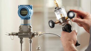
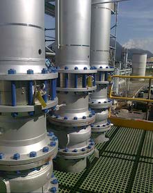
Safety systems should be designed to operate independently and reliably during startup, shutdown, maintenance, repair, and all other conditions evaluated in the risk assessment. Once the optimal pressure relief system design has been finalized, the most appropriate system components need to be determined (Figure 3).
The best solution is determined by a number of technical and economic parameters, including consideration of upstream and downstream system configurations or geometries. Some relief devices (pressure relief valves) will offer the best performance only where specific operating conditions are present. Deviations from these conditions will potentially result in unexpected performance reductions, such as chatter or failure to reclose.
The following types of pressure relief devices are used to ensure protection of installations subject to pressure:
- Reclosing devices
- Non-reclosing devices (rupture or bursting discs)
- Combination of reclosing and non-reclosing devices
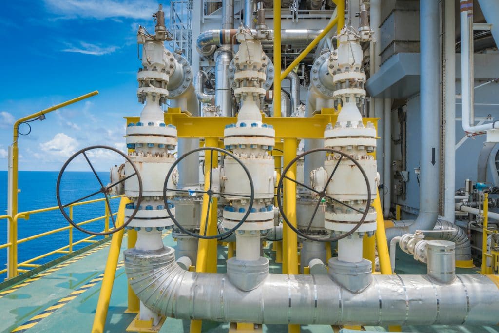
Reclosing devices (usually safety valves or pressure relief valves) allow for continued operation, even when occasional overpressures occur. Reclosing devices are preferred for primary relief applications where long-term opening of the process equipment cannot be allowed. However, they may be inefficient in applications where leakage, fouling, plugging or icing are a concern.
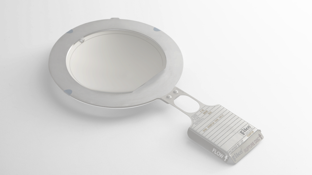
Non-reclosing pressure relief devices (rupture discs) tend to be the more economical solution, though they require that the process be shut down or redirected while replacing a burst device. In many cases, this is not an issue, and rupture discs are used as the primary relief solution. In addition, the use of rupture discs as secondary or backup systems is a widely accepted practice.
A combination of pressure relief valves and rupture discs is becoming an increasingly popular option because it delivers the advantages of both solutions. The most commonly used combination is where the rupture disc is installed upstream of the safety or pressure relief valve. In this case, the rupture disc provides a pressure and chemical seal between the process and the downstream valve. This reduces operational and maintenance costs due to leakage, repair, corrosion, etc., and it improves safety by avoiding the risk of polymerizing or plugging of the valve.
The use of rupture discs on the downstream side of safety relief valves is considered in cases where:
- Corrosion or fouling of the valve trim is a risk, such as in systems using common headers to evacuate process media, or
- Backpressure could occur on the downstream side of the safety relief valve, changing the set pressure of the safety system
When rupture discs are used in combination with safety relief valves, provisions must be made to prevent pressure build-up in the space between the valve seat and the bursting disc. Temperature changes, minute pressure leaks, and other conditions that cause an increase of pressure in this cavity may cause a dramatic and uncontrolled change in the safety system’s opening pressure.
When pressure relief cannot be applied due to environmental or safety concerns, the use of controlled safety pressure relief systems (CSPRS) or safety-related measurement, control and regulating (SRMCR) devices may be considered. However, this technology is relatively new and the systems are still in the early stages of acceptance by industry and supervising authorities, and may require specific acceptance procedures. The introduction and due consideration of safety integrity levels (SIL) is to be considered in order to achieve the required levels of safety system reliability.
Unfortunately, regardless of one’s level of experience, mistakes do happen. If an error is made in a pressure relief system design, it is imperative to learn from the error and communicate the lessons learned to ensure that the mistake will not be repeated.
Safety is the Bottom Line
A pressure safety system is typically used as the ultimate measure (“last line of defense”) to protect pressurized industrial equipment from exceeding allowable limits. It also provides a means to prevent a potentially hazardous situation from leading to injury or catastrophic equipment damage.
To provide the expected level of safety and minimize downtime, it is essential to consider not only the pressure relief devices, but the entire pressure relief system and all process risks when designing a pressure relief system. This is the best way to ensure the proper and expected operation of the safety devices as well as sustainable relieving capacity.