
The same symptoms tend to show up across applications
- Flow readings appear stable, but gas use is higher or lower than expected
- Control loops behave in a certain range, then hunt outside of that sweet spot
- Lab calibration checks confirm the meter is operating correctly despite questionable field performance
- Expected efficiency gains don’t show up after installation
Installation configuration and conditions change the flow profile and what the sensor “sees”, directly affecting the measurement.
If these symptoms look familiar, we can review your setup together to identify what’s affecting your flow measurement.
6 Factors That Affect Gas Flow Measurement in the Field
1. Installation location
Meters are often installed where the piping allows, which may not match the original design intent or provide the needed upstream diameters of pipe for a good measurement. This results in the sensor measuring a non-representative section or localized condition rather than the main process stream.
What this looks like:
- Available straight run exists, but not where the meter is installed
- Meter is located near headers, tie-ins, or transitions
- Differences between flow measurement points in the same system
How to address it:
- Compare installed location to original design or recommended placement
- Relocate within the existing pipe run to a more representative section
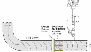
- If relocation is not feasible, use flow conditioners
2. Insufficient straight run
Straight pipe allows the flow profile to normalize before it reaches the sensor. In practice, most installations do not provide enough straight run. A single elbow can require roughly 15–25 pipe diameters upstream, and more complex layouts could require even more.
When that distance is not available, the flow profile remains distorted at the measurement point.
What this looks like:
- Good performance at low flow with increasing deviation at high flow
- Sensitive to normal process changes; pulsing, jetting, or swirl from upstream disturbances make readings unstable, often requiring damping to produce a usable value
How to address it:
- Relocate the meter further downstream of disturbances where possible
- Use flow conditioning when adequate straight run cannot be achieved
3. Distorted flow profile
Upstream components such as elbows, valves, and reducers disrupt how velocity is distributed across the pipe. Instead of a predictable profile, the flow becomes uneven, and the sensor measures only a portion of that distorted flow.
What this looks like:
- Stable readings that are consistently offset
- Differences between similar lines with different piping
- Increased noise or instability
How to address it:
- Minimize disturbances upstream where possible
- Avoid installing directly downstream of complex piping
- Where needed, apply flow conditioning to create consistent measurement
4. Gas composition mismatch
Thermal mass flow measurement depends on gas properties. If the calibration does not match the actual gas, or if gas composition varies, the measurement shifts. This is common in systems with blended or changing gas streams.
What this looks like:
- Measured flow does not align with expected consumption
- Inconsistent readings across operating conditions
How to address it:
- Calibrate using the actual gas or expected composition range
- Update gas composition settings to match process conditions
5. Moisture and contamination
Thermal mass flow meters measure heat transfer. If liquid droplets contact the sensor in the gas stream, heat transfer increases, which may result in inflated readings. If contaminants coat the sensor, measured flow may skew lower.
What this looks like:
- Unexpected spikes (liquid contact)
- Gradual drift lower over time (coating)
- Behavior that does not match process conditions
How to address it:
- Remove condensate upstream (separator or knockout)
- Maintain gas above dew point (heat tracing or insulation)
- Position sensor to shed condensate (e.g., 45° insertion angle)
- Inspect and clean sensor periodically
We can review your installation and discuss what’s affecting your flow measurement.
6. Leaks, bypass, and integration issues
Not all flow passes through the measurement point. Leaks and unintended bypass paths reduce measured flow, while signal scaling or wiring issues can introduce hidden bias.
What this looks like:
- Measured flow does not match consumption or downstream performance
- Control system response does not align with process behavior
How to address it:
- Inspect piping for leaks or unmetered bypass flow paths (leaky valves for instance)
- Confirm 4–20 mA output scaling matches engineering units in PLC/DCS
How to Check Your Installation (No Shutdown Required)
Most of these factors can be identified quickly without taking the system offline. These checks quickly isolate whether the issue is with the meter, installation, or process conditions.
- In-situ verification confirms the meter is operating correctly, helping isolate whether the issue is installation or process related.
- Check signal stability at steady operating conditions (not during transients)
- Compare sensor temperature to a known process reference
- Inspect upstream piping for disturbances, leaks, and placement issues
Closing the Gap Between Spec and In the Field
Real-world performance depends on how the meter is applied, not just how it is specified. Understanding these factors is the first step to improving measurement quality and system performance.
If your system shows any of these symptoms or conditions, it’s worth a closer review. Contact a flow expert to review your installation and identify what is impacting your flow measurement.