

Introduction
Thermal mass flow meters (TMFMs) measure or monitor the mass flow of air, gas, or a gas mixture in countless applications. Like any flow meter technology, however, there are applications where they excel and those to avoid. Understanding how the meter deviates from other measurement technologies is the first thing to understand when considering this meter style. This article reviews the critical factors to consider when determining if a thermal mass flow meter would effectively work in an application.

Thermal mass measurement vs. other technologies
Understanding the difference between a thermal mass flow meter and other measurement technologies is the first step in deciding if the TMFM is the correct device for an application.
The primary difference between a TMFM and other technologies is that it directly measures mass flow versus volumetric flow based on heat transfer.
Gas is compressible. The gas volume changes under pressure and temperature fluctuations. For this reason, orifice plates, Venturi meters, and other Delta-P (differential pressure) devices, and turbine meters, rotary gas meters, and vortex meters require additional instruments to measure the temperature and pressure, then mathematically convert the volume to mass. A TMFM does not need separate temperature or pressure transmitters as it directly measures mass flow.
The Coriolis meter is another direct mass flow meter. It is very accurate and reliable, but it is expensive and costly to install. It also is challenged in low flow, low-pressure applications when there is pressure drop.
What is mass flow?
Mass flow is a gravimetric measurement of mass moving over time, expressed as pounds per hour, kilograms per day, grams per second, or similar units. A thermal mass flow meter expresses as standard cubic feet per minute (SCFM) or normal cubic meters per hour (NCMH). Since these units of flow rate are standardized at specific temperatures and pressure, they resolve into mass flow units.
The flow meter manufacturer specifies the “S” in SCFH; that is, it stipulates the standard reference conditions for pressure and temperature. For natural gas applications, the “S” is generally 60° F and 29.92 inches of mercury, while for air applications, the “S” usually is 70° F and 29.92” inches of mercury. One SCFM of a gas (or air) at the “S” conditions represents a specific mass flow rate because there is a known number of molecules in a cubic foot of a gas (or air) at “S.” For this reason, units of SCFM, SCFH, SCFD, NCMH, are mass flow units.
Why is mass flow important?
In practicality, all medical, industrial, environmental, and commercial flow rate or totalized flow applications require the mass flow rate.
- Medical oxygen flow rate
- Industrial batching or weighing applications
- Industrial processes involving chemical reactions
- Environmental applications, such as flare gas
- Combustion control on a boiler or furnace for efficient operation
- Tenant billing or sub-metering of natural gas
A thermal mass flow meter provides mass flow directly. Therefore, there is no need for ancillary temperature or pressure measurement devices to convert to mass flow. In contrast, the previously mentioned technologies require extra transmitters, along with installation and wiring for these devices, and require calculations to convert from volumetric to mass flow.
9 benefits of thermal mass flow meters
Here are nine beneficial features of thermal mass flow meters.
- TMFMs have a high turndown ratio of at least 100 to 1, meaning that they accurately and repeatably measure a substantially greater range of flowrates over other flowmeter technologies. Additionally, on the differential pressure (DP) meter, the transmitter accuracy degrades at low differential pressures, impacting the meter’s accuracy. (See table 1.)
- A TMFM is not affected by pressure variations since it essentially counts molecules.
- A TMFM has an extremely low pressure drop (would measure in inches of water). In contrast, differential pressure devices such as orifice plates and Venturi flow meters create a pressure loss that is nonrecoverable, meaning wasted energy. A Coriolis meter (the only other direct mass flow meter) has a substantial head loss, and it too wastes energy due to its inherent geometry.
- Most manufacturers of TMFMs offer devices with extreme low-end sensitivity, capable of even detecting a pilot light in a natural gas line. In contrast, positive displacement, turbine, vortex, and differential pressure meters are incapable of such low flow rates.
- TMFMs have no moving parts. The technology depends on the heat transfer passing a pair of resistance temperature detectors (RTDs) consisting of stable platinum wound sensors protected with a stainless-steel sheath. In contrast, turbine meters have bearings that would need replacement, and positive displacement meters also have items requiring maintenance.
- TMFMs are easy to install, particularly the insertion models, which simply require a weldolet to accept the manufacturer’s isolation valve assembly. Other technologies require cutting into the pipe to insert spool sections containing the flow element.
- Although many traditional and new gas technology flow meters provide accurate flow readings over its specified range, TMFMs offer extraordinary repeatability and reproducibility with negligible maintenance, and over a broader range.
- Some TMFM manufacturers offer a simple calibration verification routine to reassure the user that the meter is performing accurately without removing the flow meter from the installation.
- TMFMs are very economical, mainly since they eliminate the cost and installation of ancillary temperature and pressure transmitters. There are also a variety of configurations and sizes available (inline style from ¼” to 4”; insertion style for pipes 1” to 18”).
| Technology | Turndown Ratio |
| Thermal Mass Flow Meters | 100 to 1 |
| DP Meters: Orifice, Venturi | 10 to 1 (at best); 5 to 1 (more typical) |
| Turbine Meters | 20 to 1 |
| Vortex | 15 to 1 |
Importance of proper installation
The location for a flowmeter installation is essential and often overlooked. Selecting a location solely based on ease of installation is often shortsighted. The end-user should consider the location’s flow disturbances before choosing the position for a meter, especially in the case of an insertion-style thermal mass flow meter. For this reason, give thoughtful consideration to determining the most suitable site. Ideally, a well-developed turbulent flow profile is required and achieved with an adequate upstream straight run. Otherwise, accuracy suffers.
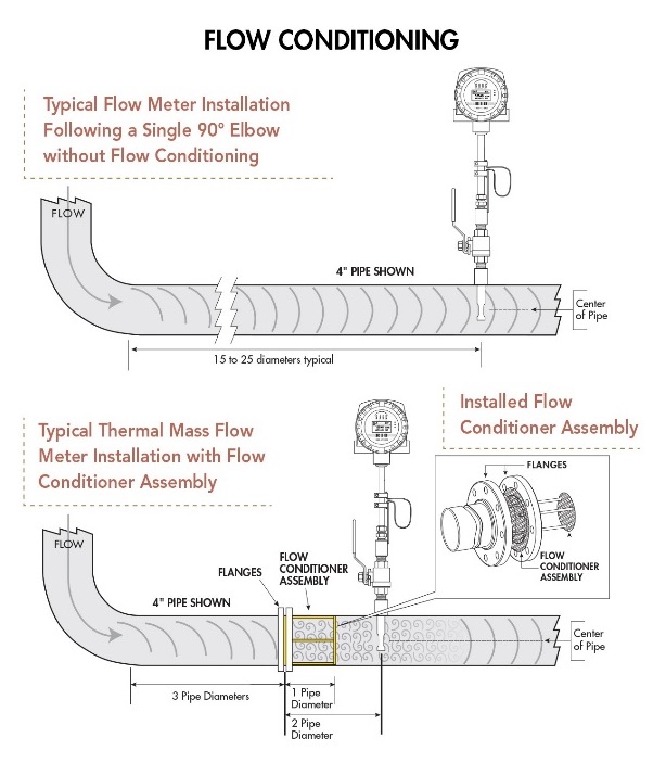
Alternatively, some manufacturers offer flow conditioning options, whether in the pipe or built-in conditioners for inline flow meters.
Once the location is selected, identify the disturbances so the manufacturer can determine if flow conditioning is required, and if so, the flowmeter would be factory-calibrated with conditioning.
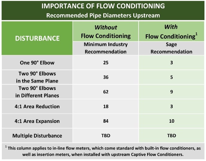
Unfortunately, most piping does not have sufficient straight run, and flow disturbances arise because of fittings/couplings, expanders, reducers, valves, tees, headers, bends, filters, strainers, knockout drums, heat exchangers, regulators, flanges, and elbows. The figure on the left is useful on how to approach some common upstream disturbances.
Selecting the proper meter and specifications
Selecting the correct flow meter for an application is the only way to guarantee accuracy. Share the application requirements with the manufacturer when specifying any meter. Here are items to consider:
- Gas or gas mix
- Pipe size and schedule, or pipe ID
- Insertion or inline style (NPT/flanges)
- Integral or remote
- Display (orientation) or blind
- Product configuration (general-purpose, explosion-proof)
- Accuracy requirements
- Flow response, temperature response, temperature compensation
- Approval requirements (Div 1, Div 2, CE, CSA)
- Standard outputs (4-20 mA of flow rate, pulsed outputs of consumption, temperature)
- Accessories (tags, software, special sensor material for corrosive gases)
- Parameters to display (flow, temperature, totalized flow)
- Communication outputs (Modbus, BACnet, HART)
- Expected full-scale flow rate (if pulse output specify pulse rate)
- Standard operating temperature and pressure (include ranges)
- Mounting hardware (valve assemblies, flow conditioners)
- A photo or drawing of the installation (optional)
Wiring Considerations
Thermal mass flow meters require power to operate, and typical options are 115 VAC, 230 VAC or 24 VDC. Some manufacturers’ meters require up to 20 watts to operate, which can become problematic if the power available is 24 VDC. Other manufacturers’ models require as little as 2.5 watts, offering the possibility of running multiple meters off a single power supply. In any case, verify there is sufficient power available to meet requirements.
Keep in mind the following to ensure that the thermal mass flow meters and the systems have sufficient wiring:
- All TMFMs provide 4-20 mA output proportional to flow rate along with other standard or optional outputs.
- Optional outputs may include pulsed outputs of consumption, temperature, and communication outputs such as Modbus, BACnet, or HART.
- Consider requirements for a SCADA system, PLC, or Building Management System.
- Is an isolated 4 -20 mA output required? If so, is the meter required to externally or internally power the output?
- When using a remote-style meter, the manufacturer provides a transducer with the flow element as well as the remote transmitter. Some manufacturers provide the custom interconnecting cable; therefore, if additional length is needed, specify when ordering.
6 applications to avoid
Thermal mass flow meters measure most gases and gas mixes, including air, argon, biogas, butane, methane, carbon dioxide, digester gas, ethylene, flare gas, flue gas, landfill gas, nitrogen, natural gas, oxygen, propane, and propylene.
As with any measurement technology, it has its strengths and limitations. Here are some challenging applications to avoid using TMFMs unless the user exercises the noted measures.
- There is an insufficient upstream straight run. An alternate location should be selected unless flow conditioning resolves the issue.
- If condensation develops in the gas stream, droplets may hit the sensors and create spikes causing over-reporting. In an insertion-style TMFM, if the droplets originate from the pipe (rather than in an atomized gas stream), consider angling the probe. By mounting the probe at an angle (rather than vertical), the droplets drip from the probe, avoiding the sensor. This measure generally resolves the issue.
- Avoid using TMFMs in widely varying gas mixtures. All NIST traceable TMFMs need calibration with the actual gas or gas mix. If the mix changes significantly, like flare gas, the heat transfer changes, and errors occur. If the mixture uncertainty (the estimated variation) is identified in advance, the manufacturer can provide a mid-range calibration and the expected error for the extreme situations. When applying manufacturer-provided K-factors, or by using manufacturer-provided software, known mixture changes often provide acceptable performance. This approach is typical for measuring biogas, and often the reduced accuracy is acceptable.
- Avoid using TMFMs in high-temperature applications (where the gas temperature exceeds 125°F). The electronics of an integral meter may fail if heated above 150° F. One solution is using a remote-style configuration, where the electronics board resides in the transmitter, rather than in the probe or flow body enclosure. Note, however, that even with a remote style TMFM, when gas temperatures reach 500°F, the standard insulation degrades within the sensor. Unless a manufacturer provides a TMFM specifically constructed for extreme temperatures (usually limited to 850°F), avoid high-temperature applications.
- Avoid corrosive gases, such as chlorine, because they damage the 316 SS sensors. Some manufacturers offer Hastelloy alternatives. In such cases, direct calibration is not possible, and surrogate gas is needed. Consequently, accuracy may suffer.
- Hydrogen and helium require calibration under pressure. Unlike other gases, errors occur when the gas pressure changes. This application requires a reasonably stable pressure, and the flow meter manufacturer needs to calibrate under pressure and, in the case of hydrogen, also contend with safety issues.
Conclusion
A thermal mass flow meter has numerous advantages over other technologies for measuring the mass flow rate and consumption of gases. Featuring wide rangeability, pressure independence, extreme low-end sensitivity, and ease of installation, they have become widely popular for countless commercial, industrial, and environmental applications. Furthermore, by offering a variety of configurations and outputs, TMFMs provide the flexibility and economy to accommodate most any type of customer’s gas flow application.
To use a TMFM to its fullest potential, give thoughtful consideration to the installation location, the meter’s flow body, and which features are best for the application.
References
- 5 factors that impact thermal mass flowmeter accuracy, flow profile and conditioning
- The future of energy management systems

About the author
Bob Steinberg is the founder, president, and CEO of Sage Metering. He has over 40 years of instrumentation experience. Before forming Sage Metering in 2002, he managed thermal mass flow meter sales at Kurz Instruments, Sierra Instruments, and Eldridge Products. While at Weston Instruments, he was a product marketing engineer. He has a BSEE and a BA from Rutgers University. SageMetering.com