


Inventory Management
Levels and weights of raw materials and finished products are often measured throughout the manufacturing process. Accuracy is vital for everything from measuring the inventory of silos and controlling the material feed/rate in batching to filling/dispensing of finished products for packaging. Maintaining accuracy can reduce operating cost, boost yield, minimize downtime and increase the percentage of manufacturing time that is truly productive.
The first stage in food production is ensuring an accurate inventory of raw materials entering the manufacturing supply chain. Reliable inventory management is essential for maintaining smooth operations, maximizing productivity and profitability, and ensuring consistent product quality. It also enables quick responses to customer needs and shifting market demands.
Accuracy is vital throughout the process—from measuring silo inventory and controlling material feed rates in batching to filling and dispensing finished products for packaging. Maintaining this accuracy helps reduce operating costs, boost yield, minimize downtime, and increase overall manufacturing efficiency.
Inconsistent and unreliable measurements at this early stage can lead to delays in delivering materials to downstream processes, contribute to production shutdowns, and result in material losses—an increasingly critical issue as the cost of raw materials like soybeans, corn, and feed grains continues to rise.
Achieving this level of accuracy depends heavily on the measurement technologies employed. Leveraging proven technologies can ensure reliable and accurate measurements, but it’s equally important to partner with instrument providers that have a demonstrated track record and a comprehensive understanding of material behavior within silos, bins, or hoppers. This alignment ensures the most suitable solution—whether non-contact level measurement or static weighing—is applied effectively.
Understanding Material Behavior
Operators, plant engineers, production managers, maintenance personnel, and plant managers all need to trust the reliability of the technologies in use. Instruments are often too quickly blamed for discrepancies, erratic measurements, and inconsistencies in critical loops. However, the root cause is frequently not the equipment itself, but rather a lack of understanding of material properties, their behavior inside a vessel, and the vessel design. Contributing factors can include silo geometry, feeder mechanism, aeration system, material flowability, silo wall friction, moisture content (which can lead to clumping), funnel flow conditions, and even seasonal impacts, among others.
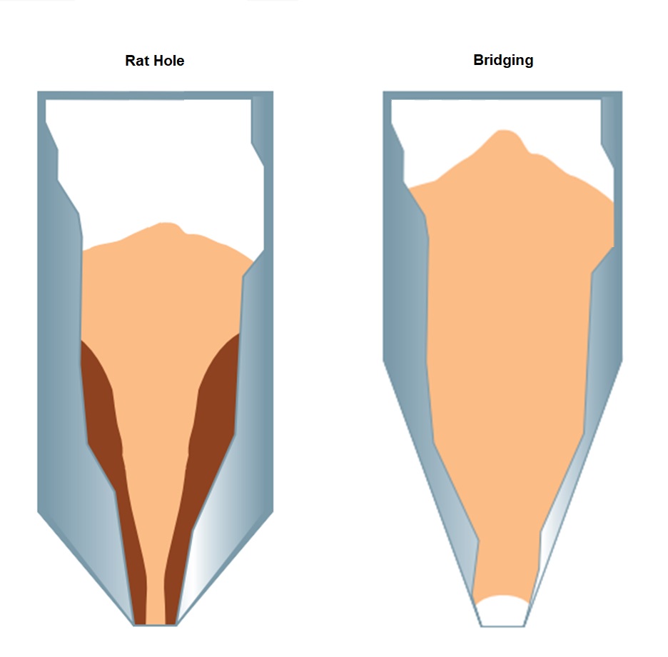
Recognizing the nuances of how bulk materials behave in silos is a complex subject, influenced by factors that may affect one facility but not another. Figure 1 illustrates some of the conditions that can occur in a silo and impact the performance of a level measurement device. It is imperative that the collective experience of both the end user and the instrument supplier be considered when selecting the ideal measurement technology.
Advancements in Non-Contact Level Measurement
Over a decade ago, high-frequency radar technology was developed to enable non-contact measurement of bulk solids in very tall silos (over 100 feet) and extremely dusty environments. This innovation reduced reliance on contact-based technologies—such as mechanical plumb bobs, guided wave radar, and capacitance sensors—as well as manual sight measurements. Contact devices often pose challenges, including frequent maintenance, risks of probe detachment due to pull-down forces, cable entangling, and safety hazards for personnel required to climb silos. Manual measurements also exposed workers to unnecessary safety risks.
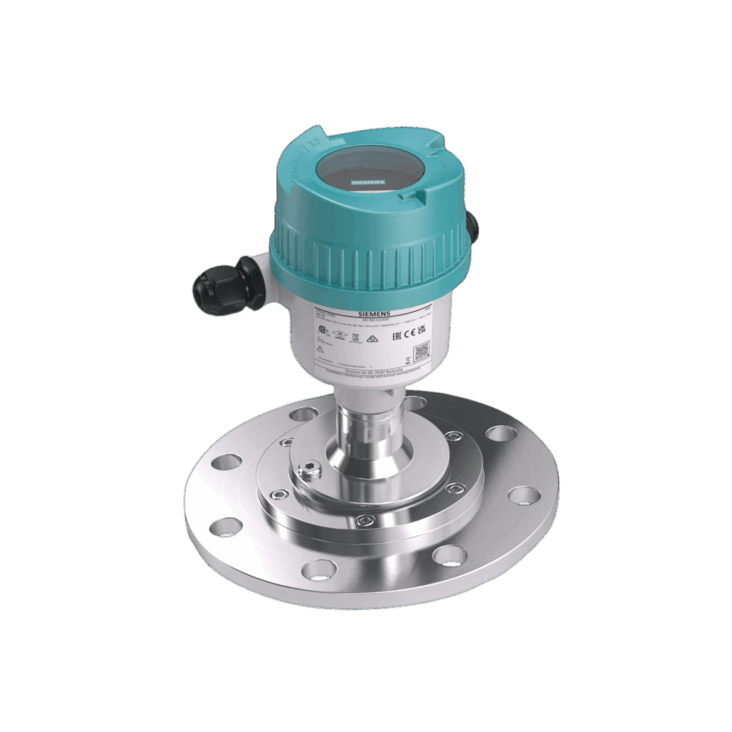
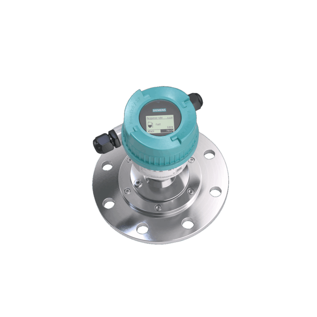
Advanced high-frequency radar level transmitters—such as those shown in Figure 2—incorporate powerful signal processing features like Process Intelligence, narrow beam angles, aiming capabilities, sensor purging (to clean the antenna lens), and built-in diagnostics. These capabilities are essential for accurately measuring in challenging conditions, including heavy dust, steep angles of repose, antenna buildup, internal obstructions, and deep-bottom cone silos.
Free-space, non-contact radar transmitters measure the distance from the sensor to the top surface of the material and are designed to perform well with many types of bulk solids. However, when the surface becomes highly irregular—with peaks, valleys, bridging, rat holes or channel flow—the signal quality can degrade. This may result in questionable or less reliable level readings under such conditions. This is not a reflection of instrument performance, but rather an indication of how the material is moving within the silo.
When Flow Challenges Persist: Considering Weighing Systems
In such cases, improving material flow can help restore reliable level measurement. Strategies may include using air to fluidize the material (to improve material flow), optimizing the outlet design, or installing a better interface between the cone outlet and the feeder discharge—such as a rotary valve—to reduce the likelihood of channel flow, especially when dealing with cohesive bulk solid materials.
However, when these challenges persist, or when a mass-based measurement is preferred for process accuracy, a weighing system may be the better solution. These systems typically consist of load cells, mounting hardware, a digital junction box, and an electronics module for seamless integration with the plant’s control system.
Silos can often range to where several hundred tons of material are stored and typically entail the use of compression-type load cells in a three- or four-point weight-bearing configuration. Selection of the requisite load cells requires a calculation of the rated, working and ultimate loads. The environment, silo geometry, overload protection, liftoff protection to limit horizontal movement and EMC protection to help guard against potential damage caused by welding in and around the vessel should all be considered in selecting the appropriate mounting hardware. The price point of analog load cells can still be leveraged for asset management when packaged with a digital junction box and electronics module for integration into any control system environment and asset information for each individual load cell.
Proper calibration of a weight measurement system is paramount to secure an accurate and repeatable measurement. The expectation is for a properly calibrated load cell system on a firm foundation to offer a 0.1% accuracy. Calibration defines the relationship between the load cell output and weight. A calibration is done by establishing two or more points on a line representative of this relationship. Because load cell outputs are linear, the weight for a given load cell output can be determined at any point on that line.
There are four main types of errors that cause inaccurate weighing: calibration errors, linearity errors and repeatability errors.
When there is a calibration error the load cell output to load ratio remains in a straight line as if properly calibrated, but that line is not representative of the actual load cell output to load ratio, and the weighing system requires a recalibration.
Linearity is all about the load cell and mounting system’s ability to maintain consistency as the load is applied. When there is a linearity error, a load cell will measure correctly at no load and full load capacity but there will be an error in between (either higher or lower than the actual weight).
Repeatability is a load cell’s ability to repeat the same reading when the same weight is applied. It reflects the maximum difference between readings and is expressed as a percentage of the applied load.
Understanding the environment like wind, rain, snow and temperature can also affect the accuracy.
It is imperative to understand the characteristics of the material while stored in a silo to determine whether a non-contact radar level transmitter or load cell package is the ideal choice. It is equally important to align with an instrument manufacturer who has a complete portfolio of solids measurement solutions – including inventory, weighing, conveyance and feeding – when addressing critical raw material inventories.
Blending Measurement Methods
Blending different components in food processing is usually done using weight. This may be done either in a batch or in continuous process. In batch blending process the flow of material is stopped when the desired amount of material is added to the mix. In a continuous blending process, material is blended without interruption to the material flow. The type of blending used will often depend on the process. Consider the process where a continuous oven is used, the ingredients will be moved from the ingredient bins to a mixing bin where they are all blended before being fed into the oven. Because the process stops for mixing this is most often done in a batch blending process. On the other hand, after the product has been cooked, nutrients or additional flavoring may be added. Because this part of the process is fed by the continuous oven, these additives may be added in a continuous process.
Batch Blending
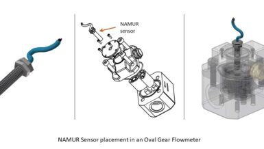
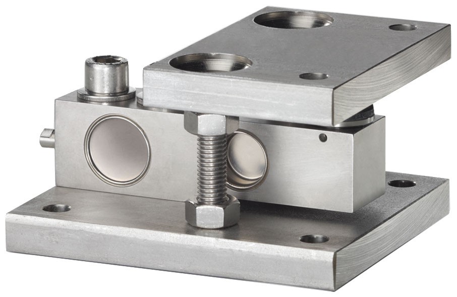
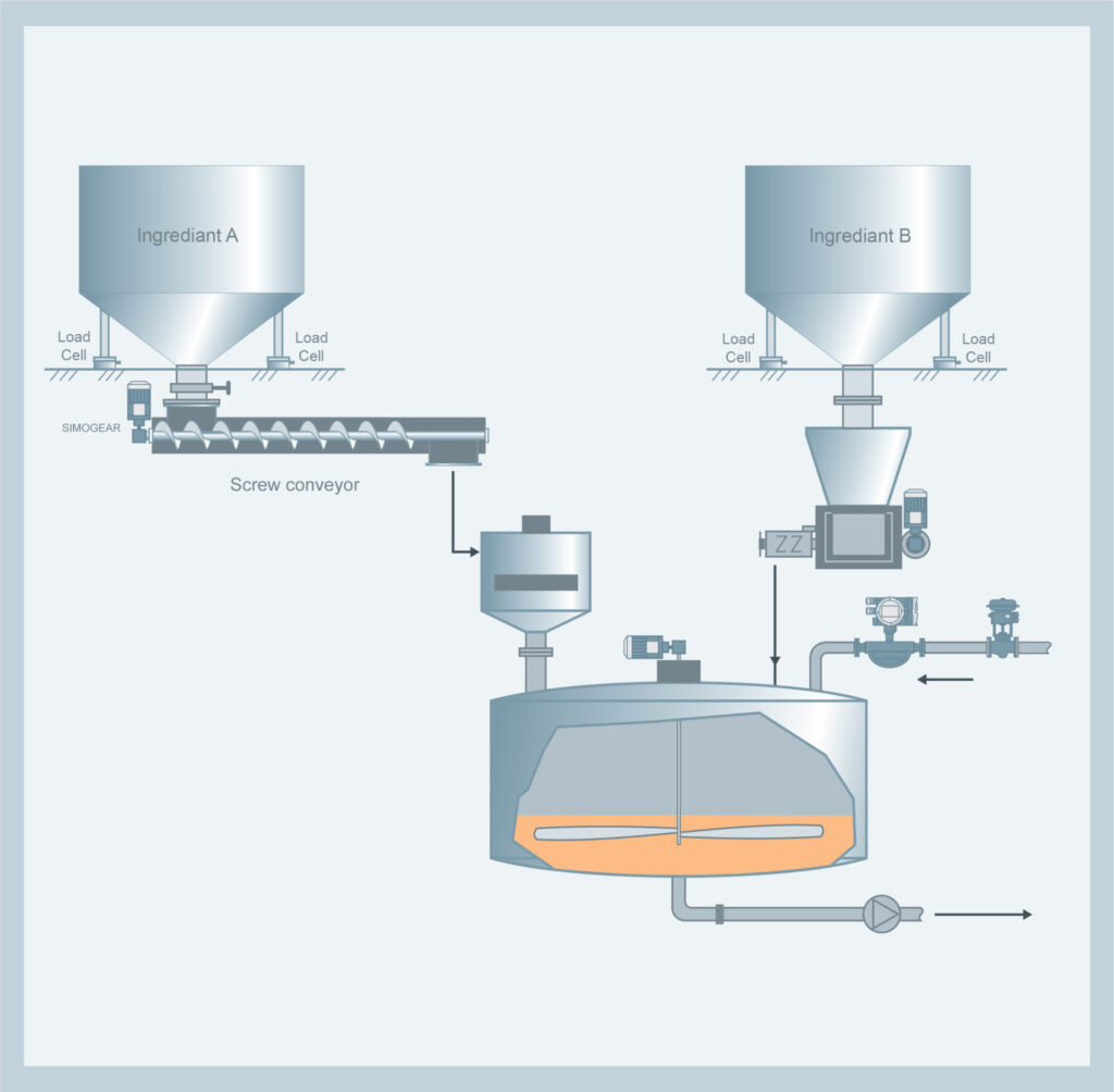
Batch blending processes can be set up two ways. In some cases, the mixing bin will be installed on load cells, similar to the load cell shown in Figure 3. The amount of material in the mixing bin is weighed as material is added to it. The weight of the mixing bin is monitored as each component is added, and when the material weight approaches the desired setpoint, the fill rate will be reduced by switching to a slower nozzle or fill stream. This type of batching system is sometimes referred to as a “gain in weight” system. Another batch blending process operates in a similar fashion, but instead of using load cells on the mixing bin, load cells will be installed on each of the ingredient bins. Liquid ingredients can be measured in the same way as the solid components or by using a liquid Coriolis mass flow meter as shown in Figure 4. The amount of material drawn from each ingredient bin is monitored and the transfer of material is stopped when the setpoint is reached. This type of batching system is sometimes referred to as a “loss in weight” system.
Modern weighing electronics can monitor the weight in the bin and provide outputs to reduce the rate of material transfer as the setpoint is approached. The weighing electronics will then send a signal to stop the transfer of material when the setpoint is reached. In addition to being able to signal a switch in fill streams, they also have the ability to monitor the accuracy of each component of the blend and adjust the next batch to compensate for any errors caused by material in the stream between the mixing bin and the ingredient bins. For example, if the proper amount of material required for the blend is 2000 pounds, when the weighing system determines 2000 pounds has been transferred, the material flow is stopped. Because there will still be material between the point the material is stopped and the mixing bin, the weight will go up slightly after the material flow is stopped. If there were 2 pounds of material left in the fill stream, the final amount would stabilize at 2002 pounds so on the next batch the material flow would be turned off at 1998 pounds to compensate for the material in the fill stream. This adjustment would be made with each transfer of material.
Because this process is critical for quality control and to maintain FSMA standards, the health of each load cell should be monitored to be certain the weighing system is operating properly. Most modern weighing electronics can monitor the health of the load cells in a weighing system; however, on multiple load cell systems the load cell signals are summed in the field and brought back to the weighing electronics as a single signal, so determining which load cell in the system requires attention may not be possible from the weighing electronics. To allow full diagnostics to each individual load cell in the system, the load cell signal is digitized in the field and the information from each cell is sent to the scale electronics. Traditionally this has been achieved using digital load cells, but because digital load cells can be costly, load cell manufacturers have recently developed field-mounted digital junction boxes to convert the analog signal from the load cell to a digital signal – allowing full diagnostics of each individual load cell without the need for a digital load cell.
Continuous Blending
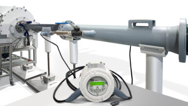
In a continuous blending system, the flow of two or more streams of material will be brought together in correct proportions. Each component is measured, and the measurement of the primary component will be used to control the flow of the other components. In solids blending applications, the material is measured using continuous weighing instruments such as a belt scale, shown in Figure 5, or a solids flow meter. If the flow rate needs to be measured and controlled, a machine such as a weigh belt feeder can be used. A belt scale or solids flow meter could also be utilized in conjunction with a separate feeding device such as a rotary feeder or screw feeder. For liquid materials, a mass liquid flow meter such as a Coriolis meter is used to measure the flow rate. Consider applying additives after being cooked in a continuous oven as discussed earlier, as the product leaves the oven, it may go through a mixing drum where the additives are sprayed in a continuous process. To determine the proper rate the additive should be sprayed into the mixing drum, as the product is transferred to the mixing drum, it is measured using a continuous scale. The speed of the additive pump will increase as the transfer rate of the product increases and decrease as the rate decreases. The rate the additive is being added is measured by a liquid mass flow meter to provide feedback to the control loop.
In a continuous blending process, conveyor belt scales and weigh belt feeders will typically provide the highest accuracy for solids measurement. However, if the material is not easily contained on a conveyor, such as fine powders, a solids flow meter may be the better option.
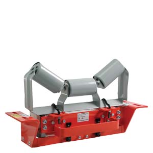
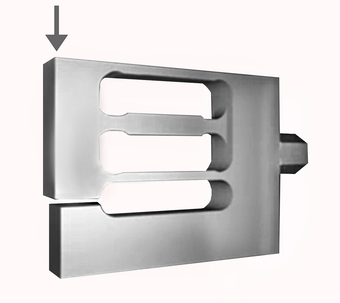
Belt scales can achieve accuracies of 0.125% and better. To achieve high accuracy, the conveyor belt scale must be designed to remove the horizontal forces on the scale created as the conveyor belt is pulled across the scale. Some belt scale manufacturers assume these forces will average out over time. While this is true to some extent, to achieve the highest possible accuracy, these forces must be mechanically removed in the scale design. Some manufacturers will use a system of pivots and levers to remove these horizontal forces, while others will use parallelogram load cells, such as those show in Figure 6. Both methods are very effective at removing these unwanted forces. Conveyor belt scale designs that use the parallelogram load cell eliminate the need for the pivot and lever system, allowing for easier installation with less maintenance.
Conclusion
Whether for inventory or blending control, there are multiple technologies available for process measurements. In most cases, weight measurement will provide the highest accuracy, but other technologies can, in some instances, meet the accuracy requirements with lower installation costs. Be sure to consider the material being measured, the required accuracy and the type of blending process to ensure you select the measurement device best suited for your application.