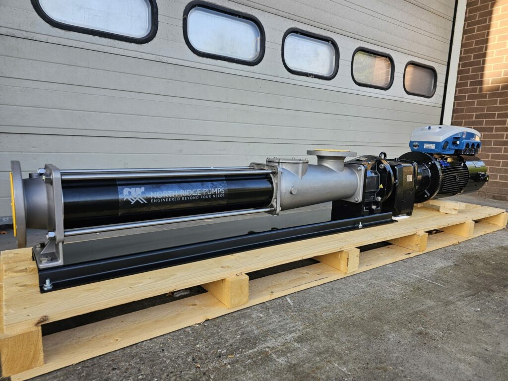
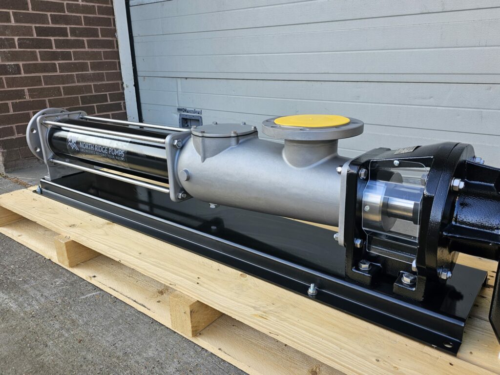
Our latest project involves a dielectric coolant pump we supplied as part of a client’s test rig. They were looking to test dielectric coolant fluids in a controlled environment in both the UK and US, meaning that the pump would have to work at dual frequencies.
A dielectric fluid can be designed for 2 purposes. To prevent and reduce electric discharges rapidly, by suppressing arcing and as acting as a coolant.
When looking for a cooling pump there are a number of criteria which determine the best pump – the required duty points, the daily hours of operation, the viscosity of the fluid being pumped and how friction losses may vary with pipe runs.
What’s more, different pump types will give different results. A positive displacement pump will transfer the same amount of dielectric fluid even if pressure losses change, for instance if the number of circuits needed to be cooled increases. In contrast, centrifugal pump flow will change according to the pump speed.
Materials used for circulation pumps can vary from cast iron for use with oils, to stainless steel, duplex metals or non-ferrous metals when used with more aggressive fluids, or to prevent cross contamination with high cost fluids, and ensure cleanliness.
In short, any pump specified for cooling should be engineered to meet any duty points demanded by the application – at both peak and off-peak demand.
Why we specified a positive displacement pump
At first, our client asked for a centrifugal pump for this application. However, we recommended that the customer look at a positive displacement pump for this process.
We selected a positive displacement pump because it would ensure flow rates would be proportional to speed, and discharge pressures would be constant. This would make conclusions much easier to be drawn than a pump in which both flow rate and pressure changed during the testing process. We would make these assessments using pump performance curves.
What is a pump performance curve?
Pump performance is governed by pressure losses in the system, with pumps producing different flows and pressures depending on conditions at the inlet. A pump performance curve is simply a diagram showing the flows and differential pressures being produced by a pump.
To enable us to specify a pump for a particular application and process, we need to know the:
- Application
- Fluid being pumped
- Flow and pressure required
- Viscosity of the fluid and its specific gravity
- Temperature
- Power available and the power medium driving the pump
Centrifugal pump performance curve
Centrifugal pumps are used in 70% of pumping applications, and their curves are generally a half-moon shape as shown above. The highest point on the left shows highest pressure but lowest flow. The far right end of the curve shows the highest flow but lowest pressure. The duty point is marked with the efficiency indicated in percentage.
Positive displacement pump performance curve
As you can see, a positive displacement curve is actually a straight line. This is because, unlike a centrifugal pump, a positive displacement pump flow is proportional to RPM and does not decrease with pressure. In addition, a positive displacement pump curve usually has a separate axis for viscosity, where the pump will show a flow against viscosity as below.
Specific client requirements
For this particular application, the client requested that the pump be able to operate at both 50Hz and 60Hz as the test rig was being used in both the UK and the US.
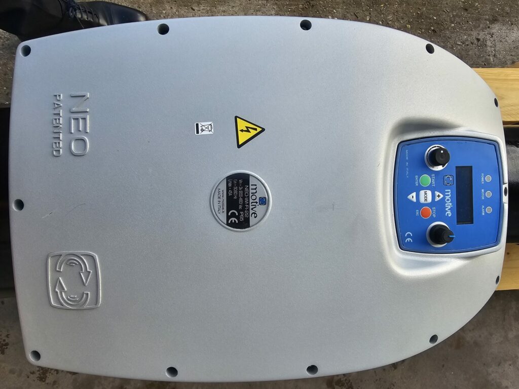
They also wanted to easily control the pump’s performance. To achieve this, we specified the pump with an integrated inverter allowing operators to adjust pump speed directly on the pump, without having to pay for an external control panel. This would enable low cost trials to be carried out without affecting the validity of the results.
If you’re developing a new product or machine, are involved in the testing of a new fluid or are looking for dielectric cooling pumps for your process, speak to North Ridge Pumps to see how we can help.


