


Therefore a consumption measurement that can measure and record the actual compressed air consumption and even the smallest leaks quickly and reliably is very helpful. If we talk about operating costs in compressed air systems, we are actually talking about the energy costs, Because the electricity costs make up about 70-80% of the total cost of a compressed air system.
Depending on the size of the system, this means considerable operating costs. Even in smaller systems, this may quickly add up to €10,000 to 20,000 per year. This is an amount which can be considerably reduced – even in case of well operated and maintained plants.
In case of a three shift operation with 200 kW compressor performance a bad compressed air distribution can create redundant energy costs of more than 50,000 € per year.
This mainly relates to the detection of leaks and the correct design of the compressed airlines to minimize the pressure losses. Energy resources like electricity, water or gas are usually monitored and therefore the costs are transparent. Contrary to compressed air, a water leak is usually found quickly due to the visibility of the leak and therefore is fixed immediately. Leakages in the compressed air network „blow out“ unnoticed, even on weekends and during production stops.
The compressors continue to run during this time just to maintain constant pressure in the network. For mature compressed air networks, the leak rate can be between 25 and 35 percent. They are the most industrious consumers working 365 days a year. Not considered in these considerations are the costs of producing clean and dry compressed air. Refrigeration and adsorption dryers dry the air with significant operating costs, which then „blow out“ useless through leaks.
With constantly rising energy costs, these energy savings have to be implemented in order to stay competitive within the market. Potential savings can only be exploited if the consumption of individual machines or systems is known and made transparent for all. However, often there is no knowledge about the leak ratio. In the following we show you how leakage rate can be determined easily in your company.
Formerly the simple but inaccurate container method was applied very often. A simplified determination of the leakages is possible by means of the emptying of the tank. To carry out this measurement you just need a clock and a manometer. Furthermore you should know the storage volume of the tank as well as of the compressed air system.
For measurement first the tank and the compressed air system are set to the upper cut-out pressure value. All compressed air consumers have to be switched off. Then the compressor is switched off and there will be no compressed air feeding into the system.
Now the time T which elapses until there is a pressure drop of 1 to 2 bar due to the leakages is measured. The pressure drop between which the measurement is taking place can be selected freely. However, in practice the described method is very time-consuming, not adequate and inaccurate due to the following reasons:
- Storage volume, distribution pipelines cannot be determined exactly
- The accuracy of the differential pressure measurement and time measurement has to be observed
- During the pressure drop, the compressed air volume cools down and therefore changes the volume flow reference value.
- An online measurement with consumption report is not possible.
This method belongs to the so-called indirect measurements, like also the method of the load and unload measurement during which the current intake is measured by means of clamp-on ammeters and calculated back to the volume flow over the technical data of the compressor. These indirect methods are antiquated and not suitable to detect leakages in the lower measuring range.
Determination of compressed air leakages with modern flow meters
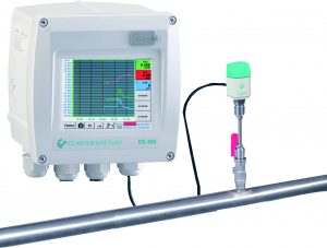
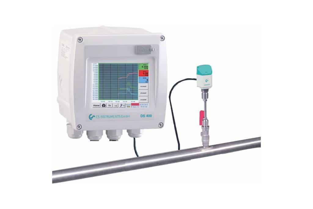
A modern compressed air consumption measurement resp. leakage measurement should be able to measure the real compressed airflow and also the small- est leakages quickly and reliably and record them. Worldwide unique with 3.5 inch, graphic display with touch screen and print function.
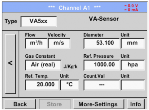
With the new ”ready for plugin” flow measurement DS 400 the current flow in m3/h, l/min etc. as well as the consumption in m3 or l can be measured. The new flow station works according to the approved calorimetric measuring principle. The heart is the flow sensor which has been proven and tested for years.
It is characterized by a new thermally more efficient sensor structure which shown a higher chip temperature in case of same electrical connection values. Compared to other calorimetric measuring instruments the sensor has a considerably lower mass and therefore a faster response time.
An additional pressure and temperature compensation are not necessary. The advantage is that the user can use the flow meters in different pressures and temperatures without any further compensation.
In addition to compressed air, other gases such as:
- Nitrogen
- Oxygen
- CO2
- Argon
- Natural gas
- Helium
Threshold value exceedance can be reported optically and acoustically. 2 relays for pre- and main alarm are freely adjustable. An alarm delay can be set for each relay. This grants that only really long-term threshold value exceedances are indicated. Additionally every alarm can be reset.
The intuitive operation with the 3.5 inch touch screen graphic display with zoom function and print key is one of its kind in the world in this price class. The graphic display with zoom function shows the actual flow, the peak values and the leakage at a glance, the values are stored in the data logger. So the user can take a look at the stored measurement curves also without any computer at any time on site. This grants a quick and easy analysis of the com- pressed air or gas consumption.
With the print key, the current screen can be saved as an image file on the internal SD card or on a USB stick and can be printed out without additional software on a PC. Ideal for documentation of the measured values/measurement curves on site. Colored measurement curves can be sent by e-mail as image files or integrated into a service report.
The internal data logger enables the storage of the measured data for several years. The measured data can be evaluated via a USB stick of via Ethernet by means of the comfortable software CS Soft Basic. Particularly comfortable is the consumption analysis at the touch of a button. The CS Soft Basic automatically draws up daily, weekly and monthly reports.
Special features:
- 3.5″ graphic display – easy to use with touchscreen
- Zoom function for accurate analy- sis of measured values
- Consumption analysis with daily/ weekly/monthly reports
- Colored measurement curves with names
- Mathematical calculation function, e.g. addition of several consumers to a total consumption or energy costs per kWh/m3
- Print key: optional indications can be stored as image files directly on a USB stick and sent by e-mail without any software
- 2 alarm contacts for threshold value exceedance
- Freely adjustable alarm delay for both alarm contacts with reset function
- Up to 4 sensor inputs for: additional flow meters, dew point, pressure, temperature sensors, electrical effective power meters, optional third-party sensors
- Integrated data logger 8 GB
- USB, Ethernet interface, RS 485
- Webserver
VA 500 flow meter for compressed air and gases
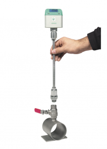
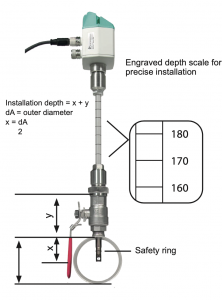
Even under pressure, the flow probe VA 500 is mounted by means of a standard 1/2″ ball valve. During mounting and dismounting the safety ring avoids an uncontrolled ejection of the probe which may be caused by the operating pressure. For the mounting into different pipe diameters, VA 500 is available in the following probe lengths: 120, 160, 220, 300, 400 mm. The flow probes are thus suitable for being mounted into existing pipes with diameters of 1/2″ to DN 1000 upwards. The exact positioning of the sensor in the middle of the pipe is granted by means of the engraved depth scale. The maximum mounting depth corresponds to the respective probe length.
Configuring the measuring site
If there is no suitable measuring site with 1/2″ ball valve, there are two simple possibilities to set up a measuring site:
- A Weld on a 1/2″ screw neck and screw on a 1/2″ ball valve
- B Mount spot drilling collar incl. ball valve (see accessories)
By means of the drilling jig, it is possible to drill under pressure through the 1/2″ ball valve into the existing pipe. The drilling chips are collected in a filter. Then install the probe as described above. Due to the large measuring range of the probes, even extreme requirements placed on the consumption measurement (high volume flow in small pipe diameters) can be met. (The measuring range depends on the pipe diameter).