


However, if this same principle is applied to other structures, mistrust quickly sets in. As far as thermowells are concerned, however, WIKA can dispel all doubts: an endurance test has now confirmed what has already been demonstrated in thousands of real applications.
Whenever there is a flow around a thermowell, two rows of vortices, rotating in opposite directions, are formed behind it under certain conditions (Kármán vortex street). These vortices could cause the thermowell to vibrate and subsequently fail under load. If the thermowell has a helix, on the other hand, this prevents the formation of a vortex street. The tendency to vibrate is suppressed in this way and the risk of dynamic fatigue failure ruled out (Scruton effect).

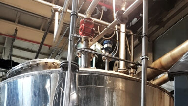
In spring 2018, WIKA commissioned a behavioural comparison of a thermowell with a ScrutonWell® design and a standard thermowell at the flow testing facility of the internationally renowned National Engineering Laboratory (NEL) in Glasgow. The test comprised a total of 47 experimental runs in a pipe containing gasoil, a diesel-like medium, which flowed over the thermowell at room temperature and at a velocity of between 0.5 m/s and 6 m/s depending on the requirements.

Fig. 2: The NEL’s flow testing facility 
Fig. 3: ScrutonWell® stem mounted in the pipe


Both thermowells were equipped with strain gauges for the duration of the test series, in order to measure the dynamic load at the transition to the flange. An accelerometer in the thermowell hole served to record the velocity values at the thermowell tip. All tests were additionally documented using a high-speed camera which provides up to 12,500 pictures per second.
Prior to commencing the tests, the dimensions of the standard thermowell were adapted according to ASME PTC 19.3 TW-2016, the calculation standard, to ensure that vibration did in fact occur in the tested velocity range, both in the flow direction (in-line resonance) and at right angles to it (transverse resonance). The ScrutonWell® thermowell was then designed in the same way. The natural frequency of the standard TW10-F thermowell was calculated as 38.7 Hz, in other words it deviated by only 4.1% from the frequency determined at the NEL by means of experiments. This result testifies to the high reliability of the WIKA thermowell calculation software V2.7.1.
Test results
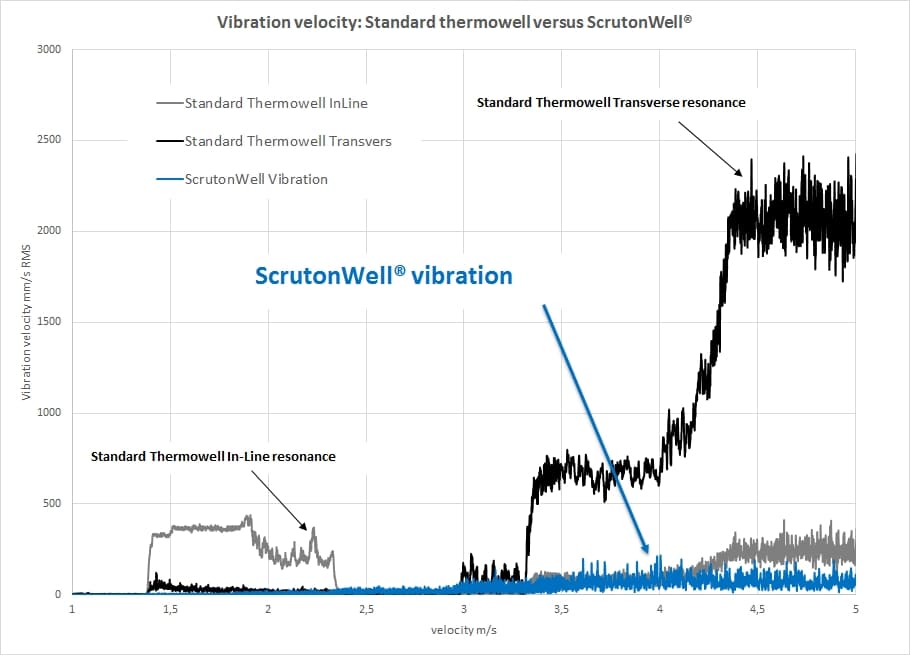
The maximum vibration measured at the tip of the standard thermowell was approximately 450 mm/s RMS at a flow velocity of around 1.8 m/s (in-line resonance, grey) or approximately 2480 mm/s RMS at a velocity of around 5 m/s (transverse resonance, black). No comparable maximum values were determined for the ScrutonWell® design (blue). Instead, the vibration increased linearly with the flow but remained permanently slight. Strain gauge measurements of the dynamic stress at the thermowell root produced a similar picture.
Thanks to the high-speed videos, it was possible to measure the vibration amplitudes extremely precisely, as shown below taking the transverse resonance for a 4.5 m/s flow as an example. Figure 5 documents the standard thermowell as having a deflection of 27 mm. The ScrutonWell® thermowell exhibits a deflection of just 1.2 mm – about 96% less – under identical conditions (Figure 6).
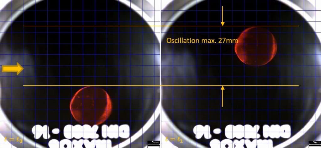
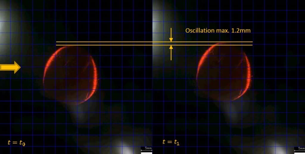
(Note on Figures 5 and 6: The dark background is due to the fact that the gasoil, which is amber-coloured when at rest (see Figure 3), became almost opaque when flowing.)
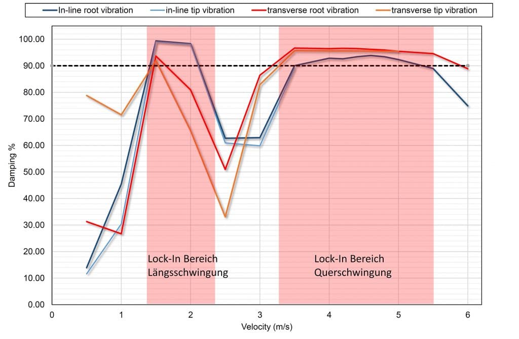
Damping
The damping of the ScrutonWell® design was demonstrated in comparison to the standard thermowell in 47 experimental runs made up of several tens of thousands of measurements. A factor ζ = (1- v ScrutonWell® / v standard-thermowell) was introduced to enable this damping to be quantified. It was decided that a damping factor ζ > 0 would identify the ScrutonWell® as superior. A value ζ < 0 would make the standard thermowell the winner of the design comparison.
According to the test (refer to the graphic below), the mean damping of the ScrutonWell® thermowell in the in-line resonance range is 90.9% of that for the standard thermowell design. A mean damping of 92.8% was recorded in the transverse resonance range. However, since the measured values exceeded the instrument measuring ranges in almost all of the transverse resonance tests, it can be assumed that the damping of the ScrutonWell® design is actually much higher.
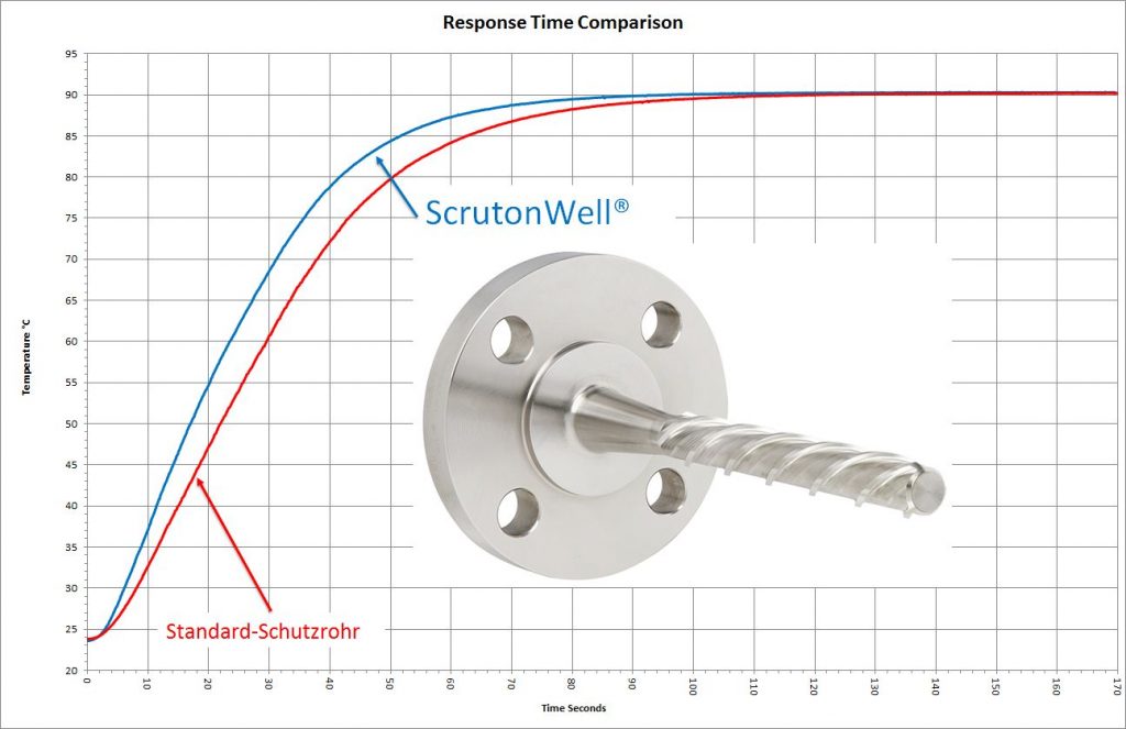
Following the NEL flow test, the comparison of the two thermowell types wound up with measurements of the response times. These times were measured in a water-glycol mixture in accordance with ASTM E644-09, the test standard for resistance thermometers. The temperature change at the two thermowells was measured at an immersion depth of 150 mm. The result: the ScrutonWell® design had a 17.6% faster response time compared to the standard thermowell (T90-time).
Conclusion
Following on from the tests carried out at the Institute of Mechanics and Fluid Dynamics at TU Bergakademie Freiberg (University of Resources) in 2014, these latest comprehensive tests by the NEL in Glasgow confirmed that thermowells with a ScrutonWell® design live up to the expectations placed in them. They thus represent a good solution whenever thermowell calculations using the ASME PTC 19.3 TW-2016 standard are problematic.
The ASME standard is an excellent way to calculate the behaviour of thermowells in fluid processes, design them accordingly and make statements regarding critical process conditions. Conversely, if the thermowell fails the calculation, its design must be suitably modified, either by shortening the unsupported length or by increasing the diameter. Very short or thick-walled thermowells may well meet the ASME requirements for mechanical strength. However, from the measurement perspective, they are a nightmare in terms of response time and precision. The need to strictly observe the flange nozzle dimensions (“interference fit”) and the thermowell’s mounting position only complicates matters further. If the thermowell is to be supported by a collar, this is of elementary importance.
Experience shows that many modifications to the thermowell design as a result of a strength calculation are outside the scope of ASME PTC 19.3 TW-2016, so that considerable time, effort and costs are inevitable for mounting. In all such situations , thermowells with a ScrutonWell® design are an attractive alternative, as has meanwhile been confirmed by several independent institutions. The helix design, proven for many years now, unites the benefits of extremely effective suppression of vortex induced vibration (VIV) with the hassle-free mounting of a standard thermowell. The static loads on the ScrutonWell® due to the flow of medium and process pressure are calculated according to the relevant sections of ASME PTC 19.3 TW-2016.