

Improved level measurement accuracy makes it possible to reduce chemical-process variability, resulting in higher product quality, reduced cost, and less waste. Regulations, especially those governing electronic records, set stringent requirements for accuracy, reliability and electronic reporting. The newer level measurement technologies help meet these requirements.
Level measurement technology in transition
The simplest and oldest industrial level measurement device is, of course, the sight glass. A manual approach to measurement, sight glasses have always had a number of limitations. The material used for its transparency can suffer catastrophic failure, with ensuing environmental insult, hazardous conditions for personnel, and/or fire and explosion. Seals are prone to leak, and buildup, if present, obscures the visible level. It can be stated without reservation that conventional sight glasses are the weakest link of any installation. They are therefore being rapidly replaced by more advanced technologies.
Other level-detection devices include those based on specific gravity, the physical property most commonly used to sense the level surface. A simple float having a specific gravity between those of the process fluid and the headspace vapor will float at the surface, accurately following its rises and falls. Hydrostatic head measurements have also been widely used to infer level.
When more complex physical principles are involved, emerging technologies often use computers to perform the calculations. This requires sending data in a machine-readable format from the sensor to the control or monitoring system. Useful transducer output signal formats for computer automation are current loops, analog voltages and digital signals. Analog voltages are simple to setup and deal with, but may have serious noise and interference issues.
The simplest and oldest industrial signal communication is 4-20 mA current loops (where the loop current varies with the level measurement) are the most common output mechanism today. Current loops can carry signals over longer distances with less degradation. Digital signals coded in any of a number of protocols (e.g., Foundation Fieldbus, Hart, Honeywell DE, Profibus, and RS-232) are the most robust, but the older technologies such as RS-232 can handle only limited distances. New wireless capabilities can be found in the latest transmitters’ signals, allowing them to be sent over tremendous distances with virtually no degradation.
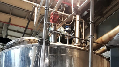
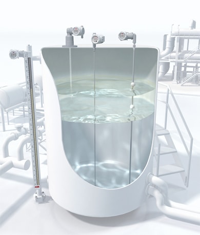
As for the more advanced measurement technologies (e.g., ultrasonic, radar and laser), the more sophisticated digital encoding formats require digital computer intelligence to format the codes. Combining this requirement with the need for advanced communication capabilities and digital calibration schemes explains the trend toward embedding microprocessor-based computers in virtually all level measurement products (see Figure 1).
Established level-sensing technologies
Throughout this article we assume the density of the vapor in the headspace (typically air) to be negligible compared with that of the process fluid. We will assume also that there is only one, uniform, process fluid in the tank. Some of these technologies can be used for multilevel applications where two or more immiscible fluids share a vessel.
1. Glass Level Gauge. Available in a variety of designs, both armored and unprotected, glass gauges have been used for over 200 years as a simple method to measure liquid level. The benefit of this design is the ability to the see the true level through the clear glass. The down side is the possibility of glass breakage resulting in spills or safety to personnel.
2. Floats. Floats work on simple principle of placing a buoyant object with a specific gravity intermediate between those of the process fluid and the headspace vapor into the tank, then attaching a mechanical device to read out its position. The float sinks to the bottom of the headspace vapor and floats on top of the process fluid. While the float itself is a basic solution to the problem of locating a liquid’s surface, reading a floats position (i.e., making an actual level measurement) is still problematic. Early float systems used mechanical components such as cables, tapes, pulleys and gears to communicate level. Magnet-equipped floats are popular today.
Early float level transmitters provided a simulated analog or discrete level measurement using a network of resistors and multiple reed switches, meaning that the transmitter’s output changes in discrete steps. Unlike continuous level-measuring devices, they cannot discriminate level values between steps.
Hydrostatic devices
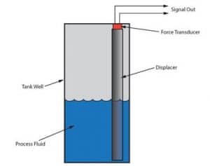
3. Displacers, 4. Bubblers and 5. Differential Pressure Transmitters are all hydrostatic measurement devices. Any change in temperature will therefore cause a shift in the liquid’s specific gravity, as will changes in pressure that affect the specific gravity of the vapor over the liquid. Both result in reduced measurement accuracy. Displacers work on the Archmedes’ principle. As shown in Figure 2, a column of solid material (the displacer) is suspended in the vessel. The displacer’s density is always greater than that of the process fluid (it will sink in the process fluid) and it must extend from the lowest level required to at least the highest level to be measured. As the process fluid level rises, the column displaces a volume of fluid equal to the column’s cross-sectional area multiplied by the process fluid level in the displacer. A buoyant force equal to this displaced volume multiplied by the process fluid density pushes upward on the displacer, reducing the force needed to support it against the pull of gravity. The transducer, which is linked to the transmitter, monitors and relates this change in force to level.
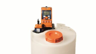
A bubbler-type level sensor is shown in Figure 3. This technology is used in vessels that operate under atmospheric pressure. A dip tube having its open end near the vessel open carries a purge gas (typically air, although an inert gas such as dry nitrogen may be used when there is danger of contamination of or an oxidative reaction with the process fluid) into the tank.
As gas flows down to the dip’s tube outlet, the pressure in the tube rises until it overcomes the hydrostatic pressure produced by the liquid level at the outlet. The pressure equals the process fluid’s density multiplied by its depth from the end of the dip tube to the surface and is monitored by a pressure transducer connected to the tube.
A differential pressure (DP) level sensor is shown in Figure 4. The essential measurement is the difference between total pressure at the bottom of the tank (hydrostatic head pressure of the fluid plus static pressure in the vessel) and the static or head pressure in the vessel. As with the bubbler, the hydrostatic pressure difference equals the process fluid density multiplied by the height of fluid in the vessel. The unit in Figure 4 uses atmospheric pressure as a reference. A vent at the top keeps headspace pressure equal the atmospheric pressure.

In contrast to bubblers, DP sensors can be used in unvented (pressurized) vessels. All that is required is to connect the reference port (the low-pressure side) to a port in the vessel above the maximum fill level. Liquid purges or bubblers may still be required, depending on the process’s physical conditions and/or the transmitter’s location relative to the process connections.
6. Load Cells. A load cell or strain gauge device is essentially a mechanical support member or bracket equipped with one or more sensors that detect small distortions in the support member. As the force on the load cell changes, the bracket flexes slightly, causing output signal changes. Calibrated load cells have been made with force capacities ranging from fractional ounces to tons.
To measure level, the load cell must be incorporated into the vessel’s support structure. As process fluid fills the vessel, the force on the load cell increases. Knowing the vessel’s geometry (specifically, it’s cross-sectional area) and the fluid’s specific gravity, it is a simple matter to convert the load cell’s known output into the fluid level.
While load cells are advantageous in many applications because of their noncontact nature, they are expensive and the vessel support structure and connecting piping must be designed around the load cell’s requirements of a floating substructure. The total weight of the vessel, piping and connecting structure supported by the vessel will be weighed by the load system in additional to the desired net or product weight. This total weight often creates a very poor turndown to the net weight, meaning that the net weight is a very small percent age of total weight. Finally, the supporting structure’s growth, caused by uneven heating (e.g., morning to evening sunshine) may be reflected as level, as can side load, wind load, rigid piping and binding from overturn-prevention hardware (for bottom-mounted load cells). In short, load cell weighing system requirements must be a paramount consideration throughout initial vessel support and piping design, or performance is quickly degraded.
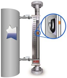
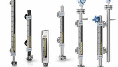
7. Magnetic Level Gauges. These gauges (see Figure 5) are the preferred replacement for the sight glasses. They are similar to float devices, but they communicate the liquid surface location magnetically. The float, carrying a set of strong permanent magnets, rides in an auxiliary column (float chamber) attached to the vessel by means of two process connections. This column confines the float laterally so that it is always close to the chamber’s side wall. As the float rides up and down the fluid level a magnetized shuttle or bar graph indication moves with it, showing the position of the float and thereby providing the level indication. The system can work only if the auxiliary column and chamber walls are made of non-magnetic material.
Many manufacturers provide float designs optimized for the specific gravity of the fluid being measured, whether butane, propane, oil, acid, water, or interfaces between two fluids, as well as a large selection of float materials.
This means the gauges can handle high temperatures, high pressures and corrosives fluids. Oversized float chambers and high-buoyancy floats are available for applications where buildup is anticipated.
Chambers, flanges and process connections can be made from engineered plastics such as Kynar or exotic alloys such as Hastelloy C-276. Special chamber configurations can handle extreme conditions such as steam jacketing for liquid asphalt, oversized chambers for flashing applications, temperature designs for liquid nitrogen and refrigerants. Numerous metals and alloys such as titanium, Incoloy and Monel are available for varying combinations of high-temperature, high-pressure, low-specific-gravity and corrosive-fluid applications. Today’s magnetic level gauges can also be outfitted with magnetostrictive and guided-wave radar transmitters to allow the gauge’s local indication to be converted into 4-20 mA outputs and digital communication that can be sent to a controller or control system.
8. Capacitance Transmitters. These devices (see Figure 6) operate on the fact that process fluids generally have dielectric constants, ᶓ, significantly different from that or air, which is very close to 1.0. Oils have dielectric constants from 1.8 to 5. Pure glycol is 37; aqueous solutions are between 50 and 80. This technology requires a change in capacitance that varies with the liquid level, created by either an insulated rod attached to the transmitter and the process fluid, or an un-insulated rod attached to the transmitter and either the vessel wall or a reference probe. As the fluid level rises and fills more of the space between the plates, the overall capacitance rises proportionately. An electronic circuit called a capacitance bridge measures the overall capacitance and provides a continuous level measurement.
Modern technologies
Perhaps the most significant difference between earlier continuous liquid-level measuring technologies and those now gaining favor is the use of time-of-flight (TOF) measurements to transducer the liquid level into a conventional output. These devices typically operate by measuring the distance between the liquid level and a reference point at a sensor or transmitter near the top of the vessel. The system typically generate a pulse wave at the reference point, which travels through either the vapor space or a conductor, reflects off the liquid surface, and returns to a pickup at the reference point. An electronic timing circuit measures the total travel time. Dividing the travel time by twice the wave’s speed gives the distance to the surface of the fluid. The technologies differ mainly in the kind of pulse used to make the measurement. Ultrasound, microwaves (radar), and light all have proven useful.
9. Magnetostrictive Level Transmitters. The advantages of using a magnet containing a float to determine liquid level have already been established, and magnetostriction is a proven technology for very precisely reading the float’s location. Instead of mechanical links, magnetostrictive transmitters use the speed of a torsional wave along a wire to find the float and report its position.
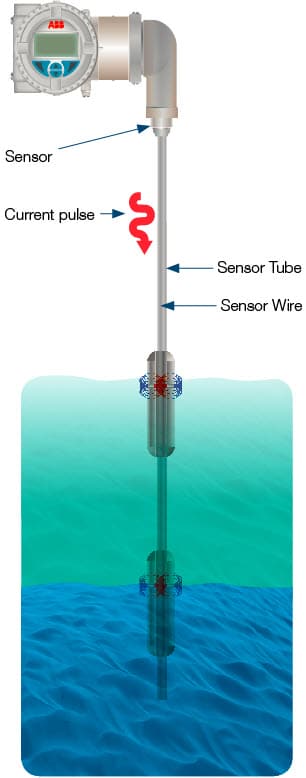
In a magnetostrictive system (see Figure 7), the float carries a series of permanent magnets. A sensor wire is connected to a piezoceramic sensor at the transmitter and a tension fixture is attached to the opposite end of the sensor tube. The tube either runs through a hole in the center of the float or is adjacent to the float outside of a nonmagnetic float chamber.
To locate the float, the transmitter sends a short current pulse down the senor wire, setting up a magnetic field along its entire length. Simultaneously, a timing circuit is triggered ON. The field interacts immediately with the field generated by the magnets in the float. The overall effect is that during the brief time the current flows, a torsional force is produced in the wire, much like an ultrasonic vibration or wave, This force travels back to the piezoceramic sensor at a characteristic speed. When the sensor detects the tensional wave, it produces an electrical signal that notifies the timing circuit that the wave has arrived and stops the timing circuit. The timing circuit measures the time interval (TOF) between the start of the current pulse and the wave’s arrival.
From this information, the float’s location is very precisely determined and presented as a level signal by the transmitter. Key advantages of this technology are that the signal speed is known and constant with process variables such as temperature and pressure, and the signal is not affected by foam, beam divergence, or false echoes. Another benefit is that the only moving part is the float that rides up and down with the fluid’s surface.

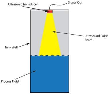
10. Ultrasonic Level Transmitters. Ultrasonic level sensors (see Figure 8) measure the distance between the transducer and the surface using the time required for an ultrasound pulse to travel from a transducer to the fluid surface and back (TOF). These sensors use frequencies in the tens of kilohertz range; transit times are ~6 ms/m. The speed of sound (340 m/s in air at 15 degrees C, 1115 fps at 60 degrees F) depends on the mixture of gases in the headspace and their temperature. While the sensor temperature is compensated for (assuming that the sensor is at the same temperature as the air in the headspace), this technology is limited to atmospheric pressure measurements in air or nitrogen.
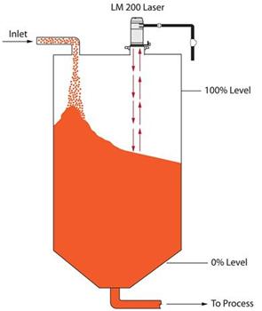
11. Laser Level Transmitters. Designed for bulk solids, slurries and opaque liquids such as dirty sumps, milk, and liquid styrene, lasers operate on a principle very similar to that of ultrasonic level sensors. Instead of using the speed of sound to find the level, however, they use the speed of light (see Figure 9). A laser transmitter at the top of a vessel fires a short pulse of light down to the process liquid surface, which reflects it back to the detector. A timing circuit measures the elapsed time (TOF) and calculates the distance. The key is that lasers have virtually no beam spread (0.2 degree beam divergence) and no false echoes, and can be directed through space as small as 2 in.2 lasers are precise, even in vapor and foam. They are ideal for use in vessels with numerous obstructions and can measure distances up to 1500 ft. For high-temperature or high-pressure applications, such as in reactor vessels, lasers much be used in conjunction with specialized sight windows to isolate the transmitter from the process. These glass windows to isolate the transmitter from the process. These glass windows much pass the laser beam with minimal diffusion and attenuation and must contain the process conditions.
12. Radar Level Transmitters. Through-air radar systems beam microwaves downward from either a horn or a rod antenna at the top of a vessel. The signal reflects off the fluid surface back to the antenna, and a timing circuit calculates the distance to the fluid level by measuring the round-trip time (TOP). The key variable in radar technology is the dielectric contact of liquid. The reason is that the amount of reflected energy at microwave (radar) frequencies is dependent on the dielectric constant of the fluid, and if Er is low, most of the radar’s energy enters or passes through. Water (Er=80) produces an excellent reflection at the change or discontinuity in Er.
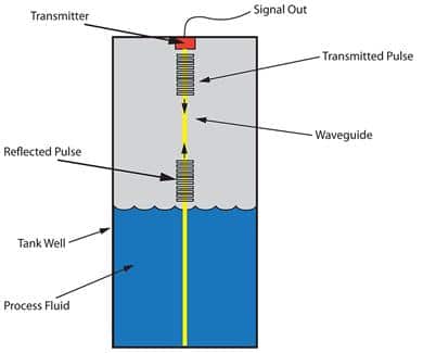
Guided wave radar (GWR) transmitters (see Figure 10) are also very reliable and accurate. A rigid probe or flexible cable antenna system guides the microwave down from the top of the tank to the liquid level and back to the transmitter. As with through-air radar, a change from a lower to a higher Er causes the reflection. Guided wave radar is 20X more efficient that through-air radar because the guide provides a more focused energy path. Different antenna configurations allow measurement down to ER=1.4 and lower. Moreover, these systems can be installed either vertically, or in some cases horizontally with the guide being bent up to 90 degree angled, and provide a clear measurement signal.
GWR exhibits most of the advantages and few of the liabilities of ultrasound, laser, and open-air radar systems. Radar’s wave speed is largely unaffected by vapor space gas composition, temperature, or pressure. It works in a vacuum with no recalibration needed, and can measure through most foam layers. Confining the wave to follow a probe or cable eliminates beam-spread problems and false echoes from tank walls and structures.
Summary
General trends across different measurement technologies reflect market drivers. Refined digital electronics are making level sensors and other measurement devices more user-friendly, more reliable, easier to set up, and less expensive. Improved communication interfaces feed level measurement date into a company’s existing control and/or information system.
Today’s level sensors incorporate an increasing variety of materials and alloys to combat harsh environments such as oils, acids, and extremes of temperature and pressure. New materials help process instruments fulfill specialized requirements as well, such as assemblies made of PTFE jacketed material for corrosive applications and electro polished 316 stainless steel for cleanliness requirements. Probes made of these new materials allow contact transmitters to be used in virtually any application.