


A contacting wet seal has a finite life that is determined by the amount of its consumable, narrow face. By contrast, a gas seal’s life cycle is limited only by the life of its o-rings, which typically last about 15 years. Compare this with the average three-year-life of a wet seal, and it is clear that gas seals merit serious attention from plant engineers and managers.
Confronting Gas Seal Misconceptions
When a gas seal is first discussed as an improvement over a traditional wet dual seal, it is often met with a somewhat perplexed and reluctant response. Some individuals are concerned about potential dangers from using gas, while others believe that gas seals have very limited applications. Let’s clear up these common misconceptions:
- Gas seals do not seal or require hazardous gases to operate
They do require compressed gas, which can be nitrogen or clean air — whichever is compatible with the process. - Gas seals also have broad applicability
They can be used in almost any piece of rotating equipment that requires a rotating shaft to be sealed.
The Emergence of Gas Seals
Before we delve into the savings achievable through the use of gas seals, let’s look at what drove the development and application of this seal design in pumps and emissions control.
In the early 1960s the first U.S. federal involvement in emission controls began with the passing of the Clean Air Act of 1970. Real regulatory limits did not make their way into law until later in the 1970s and 1980s. The first regulations established limits of 10,000 PPMs (parts per million) of gases identified as VHAPs (Volatile Hazardous Air Pollutants). Moving through the 1980s and 1990s, limits were reduced by the federal, state and local authorities to as low as 1,000 PPM and driven even lower to 50 PPM in some US states/countries. The fluid sealing industry went to work to meet these regulations, and gas seals were one of the designs arrived at to meet these challenges.
Sealing manufacturers continue to meet ever-changing regulatory challenges by improving designs and piping arrangements that maximize emissions control capabilities. We’ll discuss later how gas seals factor in the range of solutions.
Current FSA Emissions Sealing Guidelines
Below are the current sealing arrangements outlined by the Fluid Sealing Association (FSA) and commonly employed to meet regulatory requirements. It’s important to see how gas seals can meet the most stringent conditions (zero emissions) whilst also reducing energy consumption.
Emission Goal: 200PPM (FSA)
Solution: Arrangement 1 (API 682) – Single Seal

As accepted and determined by the FSA (Fluid Sealing Association), specifically designed low emission single seals are capable of effectively containing emissions to <200PPM.  These single seal arrangements are defined as Arrangement 1 in API 682.
Specifically designed single seals are an effective low emissions solution that can hold leakage to low emission rates. However, reliability depends on not just the process fluid, but other variables. Additionally, over the life of the seal (which can be several years) variables in conditions, operation and normal wear can raise the risk of early failure and increased leakage. Since there is no secondary containment, any failure of a single seal will result in high emissions. This concern leads many to the next level of protection.
Emissions Goal: 50PPM (FSA)
Arrangement 2 (API 682) – Dual Seal, Unpressurized

It is accepted and determined by the FSA that the use of the API 682 Arrangement 2, unpressurized dual seals, can effectively and reliably contain fugitive emission to the level of <50PPM.
Arrangement 2 is actually the application of two single seals in series. The old jargon, rarely heard anymore, is what used to be called a “tandem” seal. Essentially the inner seal, in contact with the process, does the actual real work of sealing. The outer seal contains the buffer fluid and is a true, installed, spare back-up seal in case of an inner seal failure. The process fluid enters into the space or cavity in between the seals and is collected, then vented to a vapor recovery system or flare. Arrangement 2 can use either two liquid seals or a liquid inner, and dry running, contacting or non-contacting, outer seal. Diligence in operations is necessary. While leakage into the buffer cavity is minimal, it still must be managed properly to control emissions.
Emissions Goal: Zero Emissions Sealing 0 PPM (FSA)
Arrangement 3 (API 682) – Dual Seal,Pressurized

It is accepted and determined by the FSA, that the use of API 682 Arrangement 3, Pressurized dual seals can effectively and reliably provide 100% containment of fugitive emissions meaning 0 PPM into the environment.
Dual pressurized seals essentially eliminate the gap in emissions levels left by the unpressurized dual seals of Arrangement 2. Like the Arrangement 2 dual seals, Arrangement 3 consists of two sealing elements. However in this case, the pressure within (or in between the two) is held at a higher pressure than the process pressure. This prevents the escape of any process fluid/emissions to the atmosphere.
Like the Arrangement 2, the sealing elements for Arrangement 3 can be either liquid, or gas barrier seals (as in the case of the Chesterton 4400 Gas Seal). Depending upon the fluid used, the “barrier,” either liquid or gas, isolates the process from the atmosphere. It thereby positively contains leakage (i.e., fugitive emissions) while maintaining a consistent, stable sealing environment. The only requirement is adequate barrier pressure above the sealing chamber pressure. This is generally recommended as sealing chamber pressure plus 1-2bar (15-30psi).
The big benefit of a gas seal in this consideration is that it provides zero emissions performance along with significant savings in on-going maintenance and energy, as we’ll discover next.
Risks vs. Benefits of Gas Seals
There are traditionally some risks associated with upgrading to gas seals. It has been demonstrated over time that gas seals are initially expensive to acquire, require complex management systems, and often need modification of the pump to be installed.
With several gas seal designs, some plants have experienced a sudden dramatic failure of associated equipment in following a loss of barrier (LOB) gas situation — and even the destruction of the gas seal itself.
However, this is not the case with all gas seal designs. Chesterton has been producing gas seals for more than over 15 years, and its 4400 product removes almost all of the traditional risks of gas seals through use of several features:
- Being a hybrid design, this gas seal is capable of liftoff at very low speeds 1.4m/s (<275 fpm) since it uses both hydrostatic and hydrodynamic lift-off mechanisms. This reduces the friction wear of the seal faces during frequent start/stop operations.
- The 4400 seal also has a management system integrated into its somewhat inconspicuous and low profile gland, the IGCS (In-Gland Control System). The IGCS removes the need for a complex gas panel. It regulates gas flow and pressure autonomously, thereby reducing the risk of premature seal failure as a result of operator control panel error or malfunction.
- The 4400 is also able to recover from LOB events without failure, protecting the associated equipment and mitigating premature seal failures. In the event of the loss of barrier gas, the seal transitions to a traditional liquid seal and recovers to a gas seal upon restoration of the barrier gas.
Applicable to almost any pump operating with a cartridge seal today, the 4400 offers users the opportunity to reach their efficiency, emissions and MTBR goals.
How Gas Seals Deliver Life Cycle Savings
To understand how a gas seal can provide efficiency improvements when installed on pumps, it is important to examine the costs of owning and operating a pump over its entire lifecycle.
The two largest pump costs are energy and maintenance. Together, these areas make up 75% of the total pump life cycle expenses. The remaining expenses are primarily engineering and the initial pump purchase.
The factors accounting for energy costs (by far the largest expense) include:
- The overall efficiency of the pumping system
- Rotational losses related to bearing condition and motor efficiency
- The energy requirements of the sealing device itself
Pump maintenance, the second largest lifetime expense, includes the ongoing replacement of items with a service life and the associated man hours to carry out those tasks.
Let’s together take a look at an example of potential savings associated with simply making a change from a dual wet seal to the technology of a non-contacting gas seal.
Comparing Power Consumption
For our example we will use a 50mm (2.000″) dual seal operating in a pump with process media at 95° C (200° F) and 7 barg (100psig).
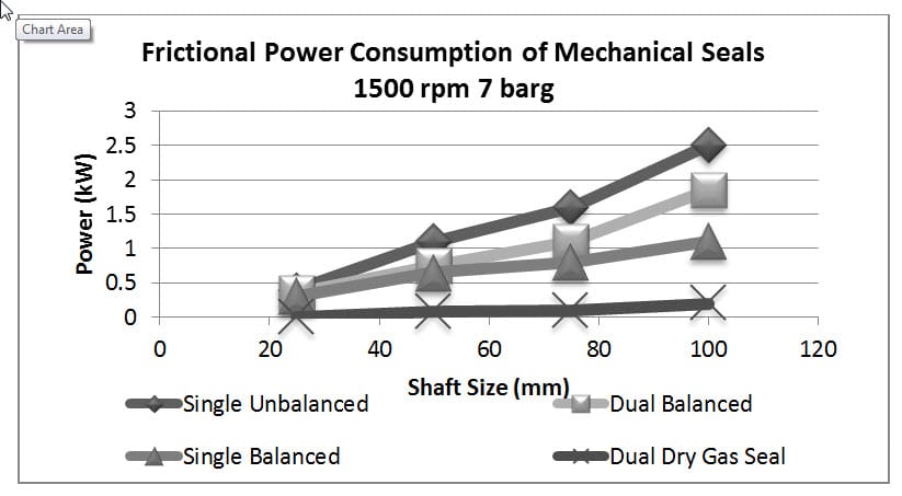
The frictional power costs can be read from Figure 1 as 0.75kW (2,600 Btu/h) and 0.08kW (270Btu/h) for the wet dual seal and gas seal respectively. Data from the UK government indicates the average European Electricity cost to be €0.08/kWh ($0.035/1000Btu/h) in 2015. Assuming our pump is operating 24 hours a day, 7 days a week, 40 weeks per year that gives us a standard multiplication factor of 6.740 hour units. The magnitude of frictional energy consumption is almost 10x for the wet dual seal versus the gas seal, meaning that approximately 90% energy consumption gains are realistic or €360 ($500) per year.
Other Benefits
When making the upgrade from wet seals to gas seals other benefits are also present:
- Product dilution cannot occur
- The risk of buffer/barrier fluid entering the process is eliminated
- There is no additional heat generated that can affect the process or, worse still, increase the need for the seal to be cooled
These factors and more based on each application can improve the overall cost effectiveness of gas seals over wet seals.
A Closer Look at Gas Seal Savings
Let us now investigate further the cost of operating a wet dual seal with a 53A pressurized barrier system, Figure 2.
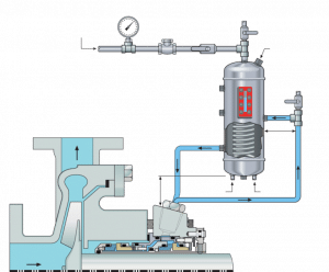
There are multiple efficiency costs at work that all contribute to the operational cost. The most notable are the frictional cost of rotating the seal and the operation of the barrier system. Its sole job is to remove heat from the seal. In our example, additional cooling of the barrier system is also required as the heat load placed on it is in the region of 0.9 kW (3070Btu/h). Add to this the cost of circulating the cooling water and the additional load placed on the plant wide cooler, and another 1.1 kW (3750Btu/h) are consumed. Thus, in total, our wet seal is consuming 2.75 kW (9400Btu) every hour it is operated.
The total the operating cost is €1.482,80 = 2,75 kW x €0,08 x 6740 h per year. In US dollar that equates to $2217 = 9400Btu x $0.000035 x 6740h per year.
As a direct comparison Figure 3 illustrates the same pump with a gas seal installed.
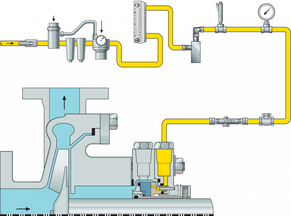
- The gas seal does not require a barrier control system. Since cooling is also not required by the seal, there is no thermal loss.
- Since plants cannot generally operate without some form of compressed air system, let’s assume that the cost of supply gas to the seal is 500w. This relates to having a dedicated compressor able to fulfill the seals gas pressure and flow requirements.
- The only other thing to add is the frictional energy cost of the seal.
The resulting saving is €1.170,06 = 1.482,80 – (0,58 kWh x €0,08 x 6740h), or $1750 = 2217 – (1979Btu x $0.000035 x 6740h)
Comparison: Costs Over a 5-Year-Cycle
Now that we know the costs of operating the seal, let’s move to the running maintenance cost based on a 5-year-cycle.
Table 1 summarizes the costs to consider for operating a Dual Wet Seal: Seal replacement, man hours to carry out inspections, barrier system top ups and seal replacements make up a large percentage of the cost. We must not forget to add in the cost of lost production.
- A multiplier of 0.6 assumes a repair cost 40% lower than the new seal cost
- A multiplier of 1.6 reflects the number of time the act of repairing the equipment would take place over 5 years (that is, the seal is repaired 1.6 times in the 5 years, meaning once every 3 years)
In total it costs more than €25,000 ($35,000) to operate a wet dual mechanical seal over 5 years.
Table 2 summarizes those same factors for the Gas Seal where we see a total cost of less than €8,000 ($11,200).
- A multiplier of 0.5 reflects the number of times the act of repairing the equipment would take place over 5 years (that is, the seal is repaired once every 10 years).
Our total savings by upgrading to a gas seal are more than €5,000 ($7,000) per pump per year. Deployed as part of a plant-wide initiative, gas seals could save pump operators literally hundreds of thousands of Euros (Dollars) each and every year.