


As is often the case in technology and even daily life, tasks can be performed in various different ways. The example of flow measurement shows how important it is to choose the right approach from the beginning. We offer the two most widespread processes for flow measurement: measuring via differential pressure and flow measurement according to the thermal principle. Other valid processes exist but are more niche. This article primarily focuses on gaseous media. Many aspects of this also apply to liquids, while others must be considered separately.
The first consideration is the difference between volume flow and mass flow. For the mass flow or discharge, the number of molecules is measured – whereas the space taken up by the molecules is measured for volume flow. Gases can be compressed, so a volume flow can change in the event of temperature or pressure changes. The relationship is described via the following formula pV = nRT. The parameters are p = pressure, V = volume, n = molar mass, R = gas constant and T = temperature. The thermal state equation of ideal gases describes this relationship. It can be well illustrated through an example with two flasks.
Why mass flow is the most precise
In order to make a statement about a mass flow, the direct measurement of the mass flow is generally the most precise option. In other processes, the flow is derived by means of differential pressure, volume flow or flow velocity. These methods, however, depend on pressure and temperature, and must be corrected accordingly. If the mass flow is the variable to be measured, an immediate measurement is usually more accurate. This direct measurement is performed by means of the thermal principle. What exactly is the thermal principle? In simple terms, the energy transport is measured. This refers to energy generated through the radiator and discharged through the flow. In this case, it is plain that it’s not volume but the number of molecules that is crucial for energy transport.
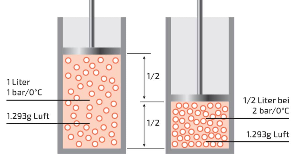
Image 1: The thermal state equation of ideal gases illustrated in the example using two flasks. A container with a volume of one litre and a movable, weightless plunger contains 1,293 g air, the ambient pressure is one bar. If the plunger moves down, the volume reduces to ½ litre. The pressure increases to two bar. The mass remains constant at 1,293 g.
These relationships make it clear that a mass flow should actually be expressed in units of weight such as mg/s or g/h. In practice, however, volume units are often used. This is not wrong as long as the pressure and temperature are specified. There are two prepared conditions for this. A pressure of 1,013 mbar and a temperature of 0°C was defined as a normal condition. This volume unit is indicated by the subscript letter n: ln/min. A second common definition for mass to volume conversion is the standard condition. This is based on 20°C instead of 0°C and is accordingly marked with an s instead of the n: ls/min. These indications of temperature and pressure are absolutely mandatory. If the difference between ln/min and ls/min is disregarded, the result is an error of about 7%. If the pressure conditions also deviate from the 1,013 mbar, the measured value can deviate even more from the true figure. Volumetric measuring equipment such as impeller counters, rotameters or turbine flow meters do not detect temperature and pressure changes. For a mass flow measurement, additional sensors for the variables as well as an arithmetic unit (microcontroller or PC) would be needed that calculates the true mass flow from all the raw measurement data. However, this is avoided and the measurement principles are usually used when an approximate measured value (not high accuracy) is required or when the volume flow is the quantity desired. Whether a volume flow or a mass flow should be measured is defined by the application itself. This is often historically limited or dependent on the industries. If purchases or sales are made by volume, volumetric measurements should be made. If, as in the case of petrol, the price factor is weight, then the mass flow should be measured.
Application-specific environmental conditions
In addition to the measured variable, which also depends on the application, the ambient conditions contribute to which sensor or which measuring principle is used. A good example is a volumetric flow controller for HVAC ventilation. There are two main factors to consider: pollution and long-term offset drift. Dust naturally accumulates in the ventilation units within homes and commercial buildings over time. When comparing a MEMS differential pressure sensor with a thermal flow sensor, it can be seen that dust has a completely different effect on the two measurement principles. Typically, a measuring orifice produces a differential pressure that varies with the flow. The pressure difference is measured with a MEMS low pressure sensor. These are usually a few mbar. However, the pressure drop must not be too high as this would destroy too much energy. Dust is not a major problem here. There is no connection between the two measuring points due to the membrane.
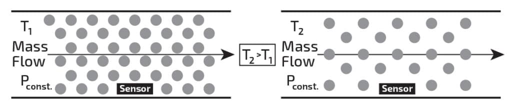
Image 2: Mass vs volume flow and temperature behaviour.
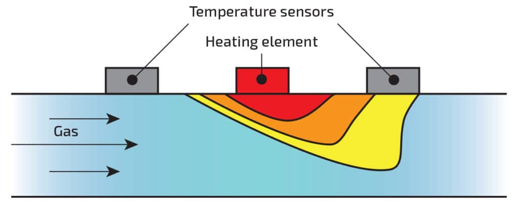
Image 3: The principle of the thermal measurement principle.
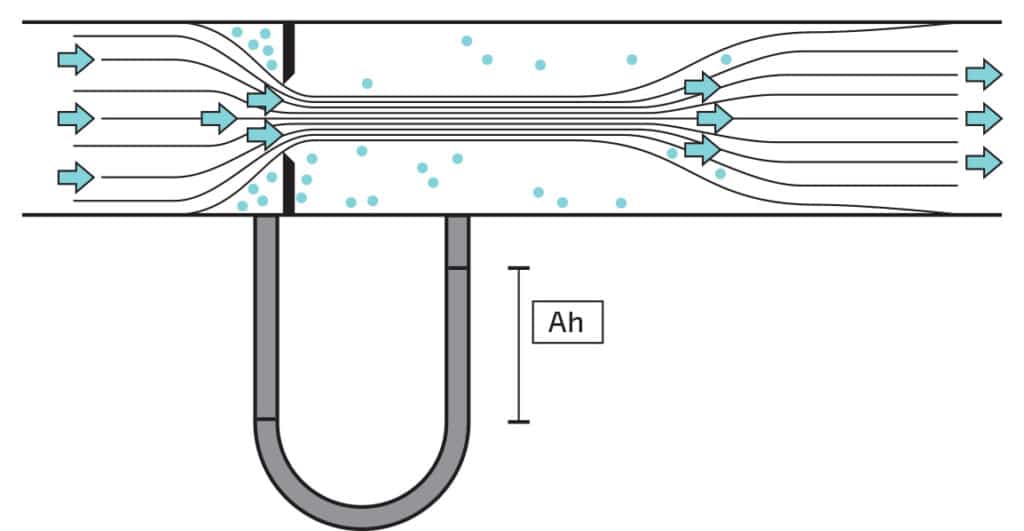
Image 4: The differential pressure measurement via measuring orifice.
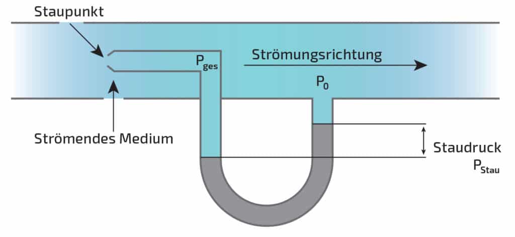
Image 5: A differential pressure measurement via the pitot tube.
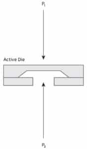
Image 6: A principle illustration of MEMS pressure sensors.
There is no flow through the sensor, i.e. the sensor cannot become clogged by dust. Thermal flow sensors work differently. These can be configured as differential pressure sensors and used in the same setup. However, they have the disadvantage that there must always be a small flow through the sensor. If the sensor is clogged by dust or dirt, the flow is interrupted and the sensor becomes defective. A filter can be placed upstream to prevent this. A filter prevents the risk of clogging, but also increases costs as well as the amount of servicing and installation work.
Despite the specified disadvantages, thermal flow sensors also offer a number of benefits. Their strength is the low long-term offset drift. Due to the principle, the offset hardly drifts over the years. As a result, no offset adjustment is necessary in the application. Due to their physical construction, pressure sensors have an offset drift – especially low-pressure sensors, some of which are even dependent on the position. In a design with a pressure sensor, it is always advisable to adjust the offset during production or commissioning and, if possible, during the entire service life. Whether or not this is possible depends on the application. If there is a known, defined state during operation, it should be used to correct the offset via software. If that is possible in an application, the pressure sensor is usually the best solution as it is more accurate and cost effective. If an adjustment is not possible, the offset drift must be taken into account in the accuracy calculations. However, most manufacturers do not specify this data in the data sheet. Some manufacturers provide this information on request.
Comparing different measurement principles
Measuring the volume for a volumetric flow controller in the context of HVAC is only one example for one application. As with any measurement task, the various measurement principles that come into question should be compared and the advantages and disadvantages considered. Depending on the application, very different concepts can be used. The price is often a deciding factor, whereby the most commercially promising solution is often chosen instead of the best technical solution. It is important to consider these aspects and boundary conditions as early as possible during development and during the design-in phase.